No. 157: A British Post (Modelu and Traversers)

Here’s a post with a decidedly British flavor.

Modelu

A few weeks ago I ordered figures from a vendor in Bristol named Modelu (pronounced Model You). The box arrived at the nearby Deutsche Post office, and my half-German wife dutifully went over there, paid the import tax, and brought the box home. Here’s what was in the box:

How exciting!

Modelu is a British vendor that makes finescale 3D-printed figures. A few guys on the Proto-Layouts list discovered Modelu online, and I offered to make a large order to try and save everyone some import tax.

Six of us combined for an over-$400 order for 60 figures. Above is shown a 1:29 figure ordered for Craig Townsend. I ordered seven HO scale figures and the other guys each ordered between five and 15 figures. The models are 3D scanned and printed to amazing detail–better than Preiser which up until now I’ve always considered the “gold standard”.

The Modelu figures are one-of-a-kind. Not only is the detail amazing but the poses are very natural, which is what I would expect being 3D scanned. This bloke, below, will go in my coal yard.

I highly recommend Modelu figures, but be careful about shipping and import taxes. The order I made was 288 Euros, which converted to $408 U.S. dollars. The Dollar-to-Euro and Dollar-to-Pound exchange rate is not working in the U.S.’s favor in the last few months, but still at about $4.50 a figure I think the price isn’t too bad.

Shipping is the “gotcha”. Modelu charges shipping, and then there’s the import tax, or “Brexit Tax” as my wife calls it. For our shoebox-size package the import tax was a whopping $105 U.S. On top of that, I sent five packages of figures to the various Proto-Layouts guy in the U.S.–another $8.50 U.S. each.

STILL…it was much cheaper to ship this way than shipping to each of us individually. Had each of us ordered individually it would’ve cost about $50 U.S. per package. So be careful when you order…make it count…

I give Modelu my highest recommendation. If you find yourself in Bristol, you can go to the shop and they will 3D-scan you, and you can put model figures of yourself on your layout. Or give models of yourself as gifts–wouldn’t that be funny. You can find Modelu online at Modelu – Finescale Figures (modelu3d.co.uk).

The Traverser

Most of you are aware that I’m building a little switching layout in my third floor train room called Hermitage Road. The room is small, and the little layout is only seven feet long. I had even less room for a staging yard, so instead of trying to cram in a traditional US staging yard with ladders on each side, I built a British-style traverser table to service the layout. See above.

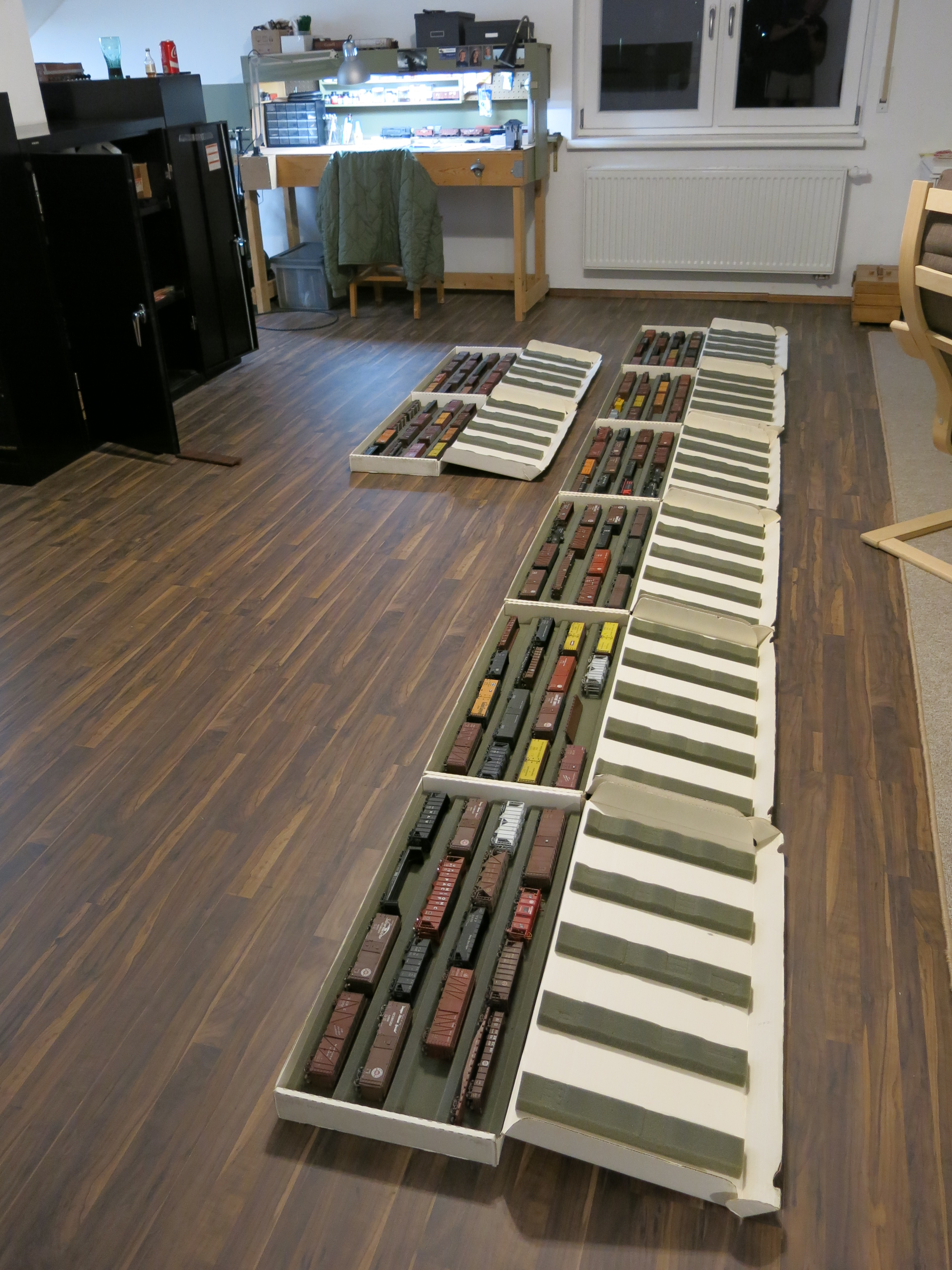
The whole traverser table is less than 60 inches long. The design has a single track to/from the layout at the left. The yard will have five tracks, each with enough room for five 40-foot cars and a single engine. There will be five short tracks on the opposite end to stage cars for runaround moves and engine storage. The thing works just like a switching yard without all the space-eating switches. I can use an open track to get around a train to push cars in, or pull cars from the end for trailing point switches.

It took me two Saturdays to build it. I made up my own plan but had to build it twice. The first version, seen below, had a 1/4-inch top. During assembly I discovered that the 1/4-inch wood top had a slight twist, which prevented it from lining up on both sides of the table. So I took the whole thing back to the wood shop on Ramstein Air Base and rebuilt it–this time with a 3/8-inch plywood top.

Here’s a photo of the first version, below, mocked up on the garage floor. You can see how small it is–compare the iPad at the top right of the photo.

Below. Here’s a photo of Version 2.0 with the 3/8-inch plywood top, taken one week later. You wouldn’t believe how much fiddling was required to get the table level on both ends. I used lots of shims of various thicknesses to get the table as level as possible for tracklaying.

I used a nice set of German ball-bearing drawer slides to provide as smooth a ride as possible. Cost: $40 U.S. for the pair. It slides very smoothly and even has a “soft-closing” feature.

Above. Here’s the second version of the table set up in position but not yet installed. The drawer slides have a just enough friction to keep the sliding table in position. It is very easy to move back and forth.

Below. Here’s a view of the layout with the traverser set up in position. The layout is just a bit shorter than seven feet; the traverser table is even shorter.

And finally, one last traverser photo, below. This was definitely worth my time and trouble. It cost about $100 up to this point, and that includes all the wood and time I had to pay for at the base wood shop ($12.50/hr). I would’ve spent that much just on turnouts for a traditional staging yard. The traverser is incredibly versatile. I’m glad I built it.

Below. Here’s the whole layout. I’m standing where the traverse table will be installed.

Hope you blokes have a great Memorial Day weekend. As you pray to our great God of power, and grace, please take a moment to remember all those fine young men that sacrificed their lives for us, that we might live free for a little bit longer.

Above: Strasbourg, France. Just as the Son of Man did not come to be served, but to serve, and to give his life as a ransom for many. Matthew 20:28

No. 153: Dave Nelson on Prototype Track Weathering

Over on the Ron’s Train Club site, Dave Nelson put together a nice post on track weathering last week and allowed me to share it here. This is a look at weathering and appearance of prototype track, not how to weather track. All photos are by Dave Nelson, but I did add a few more at the end.

Here’s Dave:

Here is a collection of track photos, with commentary, that I have used in two clinics—one on “Trackside Details” and another on “A Closer Look at Track”, neither of which I have presented since the 35mm slide era. This post will focus on track color and weathering, focusing mostly main tracks in the Midwest.

Below. There are situations where there is a very precise and clean distinction between the color of rail sides, tie plates and spikes and the ties and ballast. Even in this photo however one can see clear “rust” colors here and there on the ties themselves. The No Trespassing notice adds to the appeal.

1

Below. In some instances, rails, tie plates and spikes share a uniform coloring with the ties and with the overall appearance of the track, including ballast. This is Burlington, Wisconsin, circa 2003 on the Wisconsin Central. This line is now CN, and was originally Soo Line. In this photo there is a near uniformity of color between rail sides and ties, including ballast between the rails.

2

Below. This is the Union Pacific (ex-C&NW) “New Line” in 1999, photographed immediately after a wreck which caused the scars on the tie and tie plate. The tie has an unusual red hue.

3

Below. In this 2017 photo from Ackerville, Wisconsin on the Canadian National, the entire track structure on the left displays a rusted coloration. My hunch is that the track on the left is on a grade and this is an area of heavy brake application.

5

Below. This 2003 photo is at the CP at Waterford Avenue in South Milwaukee. This is former Milwaukee Road right-of-way. Note how the rusted rail sides has stained the ties and ballast.

7

Below. What is striking about this photo from Galesburg, Illinois on the former Burlington lines is that the wood ties basically share the same color as adjacent steel ties. The steel ties seem to be moving around a little bit too. I can’t really call the ties black or brown – they are box car-reddish.

8

Below. Of course external factors can also be at work, such as this track in Galesburg in 2003 where the “lurch” at the switch to the Quincy Main has caused many loaded ore cars to dump bits of taconite on the tracks, lending a reddish shade to everything.

9

Below. Another external factor is when a freight car sits for a long period, the wheels and the car sides rust and that rust ends up on the ballast and elsewhere. An ex- C&IM gondola at Milwaukee’s Miller Compressing facility in 1986. Note the “drip line” beneath the car side!

10

Below. Wheel greasing also creates its own shades of course. What a greasy mess!

11

Below. Here’s a John Golden photo on the Indiana Railroad, formerly Monon. A pad has been put down at the point of a flange oiler to protect the ballast and it’s doing a great job. I’ve never seen this modeled.

Monon, Orleans, IN (10)

Below. This is a photo of a mainline with mud pumped up through the entire track structure. Silt and dirty ballast has found it’s way to the top of the ties, which has it’s own colors which show on ballast, ties and rail sides.

This is seen most often at crossings because those areas tend to be left alone by track gangs for economic reasons. This is 2007 on the CP near Portage, Wisconsin, on the former Milwaukee Road lines. This is almost never modeled.

12

Below. 2014 on the BNSF along the Mississippi River in Wisconsin. This is an extreme example of mud pumping up through the ballast due to flooding and plugged culverts. Note how it is only in a specific area on the track.

13

Below. This is 2014 on the Santa Fe, now BNSF, between Cameron and Fort Madison, Illinois. Note the clear demarcation where the subroadbed has failed and is pumping up mud, near but not at a crossing.

14

Below. This photo was taken on a former Milwaukee Road branch at North Lake, Wisconsin. The line was sold to a tourist railroad for a while but that operation is now closed. Most of the rail rolling dates date well back in the 19th century along here. Note the ballast is made of rocks, dirt, cinders, and whatever was available at the time.

15

Below. Matt Goodman has done a great job of modeling this type of ballast on his switching layout. Here’s a photo from Matt’s Flickr site:

Matt Goodman 1 (6)

Wood timber crossings have always been a special interest of mine. There were two in my home town and both were on heavily traveled roads with lots of trucks. The timbers were loose and the crossings were really in bad shape no matter how much attention the C&NW paid to them.

Below. I took this photo in 1997 on the BNSF at Gilson, Illinois between Galesburg and Peoria. This was at a lightly-traveled rural road. And yes, the automatic crossing gate was somehow not working in time even though (or because?) the train was moving very slowly.

16

Below. A very rough road crossing in Earlville, Illinois, where the UP (ex-CNW) Troy Branch line crosses the BNSF ex-CB&Q main. This would never be modeled because it just doesn’t look prototypical.

17

Below. Pedestrian crossings were very, very common in the Midwest. I don’t remember where I took this photo—probably somewhere in Illinois. Note the very narrow sidewalk.

18

Below. Here is a nice timber crossing at a skewed angle on the Iowa Interstate, ex-Rock Island, west of DeSoto, Iowa. I had won a drawing for a cab ride.

19

Below. Another nicely maintained timber crossing, this on the BNSF line between Galesburg and Peoria, Illinois on the outskirts of Yates City which was at one time a major junction point. This view demonstrates why culverts and ditches are so important to realism in modeling.

20

Thank you, Dave for another great post.  I certainly learned a lot!  Here, below, are a few additional photos that I’ve taken over the years.  The shot below is on the CSX lines in Vidalia, Georgia (former SAL).  Note how the ties around the moving switch points are mostly clear of ballast.

IMG_4130

Below.  This is another photo along the CSX lines, near Helena, Georgia.  The contrast between the rusty rails and the old ties is interesting.  Modeling ties that are deteriorating is a challenge.

IMG_4240

Here’s a closer view of a different tie. No spikes on this one.

IMG_4173

Below. This photo is from the Rancocas Industrial Park, near my former home in Mt. Laurel, New Jersey. The roadbed and ties have completely sunken into the ground. The top of a few ties are still visible. This is very difficult to model convincingly.

IMG_2671

Below. I’ll finish Dave’s excellent post with this lovely picture, taken a few miles north of Albuquerque in 1998. Looking straight down at the track one can see different colors of rail, ties and ballast, but looking at the long view–to the horizon–everything blends together into one rusty color.

Albuguerque Area 1 (18)

And a Post Script: Here’s a recent photo from my adopted country. Date nails are rare in the US any more, but they are still found everywhere in Germany and Europe. Here is a tie on retired track with five nails. One is certainly the date nail–the others I’m not quite sure about.

IMG_2332

In these troubling times, look to Psalm 37:3 for strength and reassurance:
Trust in the Lord and do good;
Dwell in the land and cultivate faithfulness.

Source: https://bible.knowing-jesus.com/topics/Trusting-God-In-Difficult-Times

No. 149: Display Cabinets for the Train Room

Over the recent Labor Day weekend–when covid restrictions were relaxed and travel to France was still possible–I took a day of leave and went to Verdun, France, site of the tremendous, 11-month-long German army assault during World War I.  I visited the excellent War Museum there, three vast graveyards, many of the battlefields, the Ossuary, and Ft. Douaumont.  It was a beautiful day but a very sobering learning experience.  It’s hard to believe it was real.

IMG_2818

Above.  Some of the trench lines still exist.  They can be found all over the place.  This one, near Ft. Douaumont, has been preserved to a certain extent.

Incredibly, all the land in the area still looks like this, below–completely chewed up by a year of constant artillery fire.  Deep in the newly-planted forests, the land is still pock-marked.  They said 130,000 bodies are still out there somewhere.  Again, it is hard to believe it was real.

IMG_2836

There is one German cemetery nearby, with over 5,000 dead, and a monument to ten thousand more…

IMG_2156

The Battle of Verdun Museum is clean and modern and very well done.  An English language site can be found here: Mémorial de Verdun. A museum and a memorial to the Battle of Verdun (memorial-verdun.fr).  Among the fascinating displays are helmets and equipment found on the battlefield with bullet holes shot through them.  This change purse, carried into battle by a French soldier, was gifted to the museum.

IMG_2195

Near the trench lines is the Ossuary, the big building in the background, which is the largest monument to the French army and their sacrifice.  In front is the largest of the French war cemeteries.  Many of these graves have the remains of multiple men.

IMG_2219

The Ossuary is famous as the repository of human remains found on the battlefield.  Since the end of the war, remains have been dug up by salvage crews and souvenir hunters, and if the remains can’t be identified they are brought to the Ossuary for internment.  The basement of the entire building is full of these small rooms, seen below, each holding scattered remains.  I really didn’t want to look in the basements, but felt like I had to.  Here is a photo of one of the many rooms below.

IMG_2212

Well, you didn’t visit the blog to see bones, so let’s get to the modeling stuff.

Back in August, after my son left for college, I determined that I had nothing to show my modeling to visitors.  I embarked on a small program to build displays and a small switching layout.  It had been a year since I moved from Albersbach and dismantled the Ackley layout for parts, and there was no place to showcase my work.  

The first project was to build two wall-mounted display cases, a small one for eight pieces of HO rolling stock to fit in a specific place on a wall, and a larger O scale display that holds ten pieces of rolling stock, designed to fit on a wall on the stairwell to the train room.  The small HO display is below.   I made it from 2-1/2-inch-wide specialty wood and painted it the same color I used for the Ackley layout fascia.  I’m able to use the “Wood Shop” at Ramstein Air Base so I have access to all kinds of woodworking equipment. 

IMG_2709

I also built two small “display shelves”.  I saw a similar design online on a Japanese modeling site, and modified that design to produce an HO scale and an O scale display track.  Each display has track, ballast, and static grass on a finished display with a small fascia around all four sides.  The HO display was finished first.  The O scale display was built to Proto48 fine-scale standards and all the track had to be completely handlaid, including laying down scale ties, tie plates, rail and the works.

Here is the HO scale display shelf under construction, below.  This isn’t the best photo, but it’ll give you an idea what it looked like before I installed track.  I used a piece of 3/4-inch plywood leftover from a bed-making project, and attached a short Masonite fascia around all four sides.

IMG_E2358

I installed N scale roadbed, then Micro Engineering Code 55 flex track.  I painted the rail, ballasted the track and added static grass.

IMG_2360

The finished display is below.  The lighting is poor, but you get the idea.  Now I have a small, weathered, model display track that I can put anywhere in the room, or I can even hang it on shelf brackets.

IMG_1992

The Proto48 display was a lot more involved.  The concept started the same: A heavy piece of plywood, sanded and painted, and dressed on all four sides with very short Masonite fascia.  Below, I have made a roadbed from low-profile cork from the craft store, and am laying O scale ties.  The initial coat of paint used on the ties was Testors Rubber.

IMG_2367

Here are the ties.  I used Grandt Line parts for all the track details, and Right-o-Way Code 100 rail.

IMG_2365

Below.  Here’s the old man himself, installing ballast on both the HO and O scale displays.  I ballasted both displays using dirt I brought over from the site of the PRR roundhouse in Richmond, Indiana. 

IMG_9480

Below, I have added static grass and also added a little Woodland Scenics foam on top.  Next comes the hard part!

IMG_E2386

Below.  Adding tie plates and 39-foot sections of Code 100 rail.  I pre-painted the tie plates and rail with Tamiya Medium Brown.

IMG_2388

Below.  With the rail spiked down, I tested the gauge with a pair of Rich Yoder trucks.  Works good!

IMG_2390

Here’s a snap of the display track all finished and on top of some bookcases.

IMG_2225

Models look nice on display here.  This is a modified Intermountain car kit.

IMG_2227

I also built a Proto48 display cabinet for the stairwell leading to my third floor train room.  Again I used specialty lumber from the local German do-it-yourself store, Hornbach.  It turned out well.

IMG_2224

Both displays turned out very well and I finally have some nice displays so show off some models on those nights when the boys come over for a beer.

The last display I mentioned is construction of a small switching layout.  I tried for months to design a switching layout around the Milwaukee Road’s Mason City, Iowa freight house, but I couldn’t design something satisfactory in the space available. 

I also tried to design a very small, Midwestern-themed, end-of-the-line layout.  I wanted to model the Milwaukee Road at Preston, Minnesota but again I couldn’t fit everything I wanted into the space available.  Below, the Milwaukee Road station at Preston, Minnesota, circa 1965.  Photo courtesy the Midwestern States Archive.

IMG_9898

Finally, after I decided to go back to my Seaboard Air Line roots and build a very generic, “composite” layout based on the switching district located next to SAL’s former Hermitage Yard in Richmond, Virginia.  

Below.  Here is SAL’s small Hermitage Yard in Richmond.  Photo is looking north.  Just behind the diesel engine house in the background is the switching area being modeled.  Photo circa 1964 by Bill McCoy. 

SAL 1474 Hermitage Yd., Richmond, VA 12-57

That layout is well underway and I’ll post some information on it very soon.  I’m building the layout in the British cameo-style and so far I love the results.  

IMG_2044

Merry Christmas!  May God bless you and your families this Holy-Day season!  – John


No. 140: New Turnouts for a New Layout

IMG_9752 (1)

I spent all last week in Mezraya, Djerba Island, Tunisia, leading U.S. participation in a small international airshow.  Djerba is a sleepy report island in southwest Tunisia near the border with Libya.  It was a great experience and as always the Tunisian people were friendly, happy and grateful.  It was a long week—many 12+-hour work days.

The photo above shows a few of the jets we brought down.  In the foreground is Air Force KC-135, at center is an Air Force C-130J, and farthest away—with the number 426—is a new Navy P-8.  The team and I flew down on the C-130.

Below.  Here is a photo of me with one of the Tunisian C-130 crews before the air show started. I’ve been working with these guys for a long time and they’re my friends.  The Tunisians consider themselves “European Muslim” and they don’t get into all the jihad crap.  They love America.  Their military is full of well-trained, well-educated women too, like Capt Lajnef at center.  They all speak Arabic, English and French.  My French—all 25 words of it—got a serious workout.

IMG_9806 (1)

I won’t bore you with all the stories from the airshow but it was a great event and we met a lot of great people from 28 countries.  Our hotel on the beach was nice too…

IMG_9673

…and no visit to Tunisia would be complete without a visit to a nearby grocery store to stock up on red wine and olive oil.

IMG_9908 (1)

I brought a model along but had little time and no energy to assemble it.  However, over the last two months I’ve accomplished a lot of new work on track for the next layout.  Here are some photos of the work.

On my late Ackley, Iowa layout I built turnouts using Central Valley tie strip and Proto87 Stores parts. I used Printed-Circuit-Board (PCB) ties for throwbars.  If the turnouts had any weakness it was the throwbars, as it took a whole lot of work to repair or replace a PCB throwbar.

Turnouts for the new layout—whatever that layout will be—are already being built.  Until I decide what to build I’m building a large variety of switches using mostly items I have on hand, knowing I will be able to use some or all of them.

IMG_8379

This time, I’m building turnouts using three different methods:

  • Scratchbuilt using CV ties and P87 Stores parts
  • Kitbashed using a Micro Engineering turnout with replacement frogs and P87 Stores parts
  • Kitbashed using Shinohara turnout as a starting point, and replacing almost everything

I’ll start the picture show with the Shinohara turnouts.  You know Shinohara turnouts aren’t DCC-friendly and the details are not up to today’s standards, but they’re cheap and plentiful and are the only way to get a wye unless you want to use a Fast Tracks or other system.

Below is a totally rebuilt Shinohara Code 70 #4 left.  From left to right, I added a few Central Valley ties, then replaced the Shinohara throwbar with a Micro Engineering Code 70 #6 throwbar set trimmed to fit.  I attached the throwbar to the closure rails with Code 70 rail joiners to provide a tight fit and better electrical connectivity.  The white metal detail parts are from Details West.  The joint bars are from Details West and Grandt Line.

The frog is a replacement part from Proto87 Stores.  It was easy to cut and dig the original frog out, but I had to be really careful when it came to trimming the rails to fit the new frog.  I added a few more detail parts from Proto87 Stores and also a few more Central Valley ties on the diverging rails.  The work took about 2-1/2 hours.

IMG_3649

Here’s a much more complex rebuild.  This is a Shinohara Code 70 #4 Wye.  About all I kept was the rail.  I have replaced most of the ties, and the frog and throwbar are all completely new.

IMG_3633_Moment

Below.  Here’s a closeup of the throwbar.  I replaced the ties in front and behind with Central Valley ties.  To do this, I first installed an underlayer or .005 styrene and then slid each tie in position one by one.  The throwbar is a PCB tie from Fast Tracks, soldered to the point rails that were originally installed on the turnout.  The header ties are Micro Engineering wood ties.  The detail parts are from Details West.  The tie plates are from Proto87 Stores and are applied to wood ties that have no detail.

IMG_3634_Moment

This one isn’t finished yet of course.  I just recieved the replacement #4 frog from Andy Reichert at Proto87 Stores a few weeks ago and haven’t had time to install it yet.

Someday soon I will rebuild this Shinohara Code 70 #8.  I originally installed this turnout on a small layout I built in my first house in Charleston, South Carolina way back in the early 1990s.  I don’t know if I’ll ever use this turnout, and it’ll take a whole lot of work to complete, but it’ll be nice to have in case I ever need it. 

IMG_3636_Moment

I’m also building turnouts using Central Valley (CV) tie strips.  This is an easier process but usually requires that I file my own point rails, which is time consuming.

The turnout below is a Code 55 #5.  Not commercially available of course–hence the challenge.  The tie strip is a Central Valley product, and the rails are all cut, filed and fit by yours truly.  The frog is from Proto87 Stores.  Like the Shinohara turnout above, I used rail joiners to join the point rails to the closure rails.  To provide a level track surface using the rail joiners I use a miniature round file and file a divot in the ties underneath the joiner.  The ties are each end are Central Valley.

IMG_3648

Another Code 55, #5 is below–this one a left hand.  I have added some details to the throwbar.  From Zero to Finished and Totally Detailed, the build for these turnouts takes about 2-1/2 hours.

Below.  Here’s what the workbench looks like when I start.  Gotta have the Lego horse–that’s a top priority.

IMG_8462

Here is the Code 55 throwbar and point-set after construction.  It probably takes 10-15 minutes to file the points to shape.  Then I use masking tape to secure the point rails in place on top of the PCB tie—ensuring the rails are completely 90-degrees vertical (that’s VERY important!)—and then I solder them in place.  The line cut between the rails is done with a motor tool with a cutting disk to isolate the rails.

IMG_8480

Here’s another Code 55 turnout.  This one has a few more details installed.

IMG_3644

This photo shows one of the Code 55 turnouts with Proto87 Stores joint bars installed.  The joint bars disappear when the turnout is painted, but magically reappear in closeup photos.

IMG_3647

The hardest part of building these turnouts is getting the frog in the right position, and it’s not all that hard, really.  I lay both outside rails and then position the frog so that it is in alignment with both outside rails.  The Central Valley tie strip is built to make this process easy.

IMG_8400

Below.  Here is a Code 70, #6 turnout built from Central Valley tie strip and mostly Proto87 Stores parts.  The frog is a re-used part from the Ackley layout.

IMG_3635_Moment

The easiest turnouts to rebuild are Micro Engineering switches. On Micro Engineering turnouts I replace the frog with Proto87 Stores frogs and add some detail parts, and that’s it.

Below.  The turnout on top is a Micro Engineering Code 70 #6 right out of the package.  It’s a great product.  Below it is a rebuilt Micro Engineering turnout with a Proto87 Stores “Manganese Frog” and some additional detail parts added.  No header ties are installed yet.

IMG_3639_Moment

The advantage to using Micro Engineering turnouts as a starting point is the detail level is good, and the throw bar is durable.  Digging the ME frog out is easy.  Here, below, is  Code 70 #6 right with a replacement “Manganese” frog from Proto87 Stores.  The new frog was glued into place with Gorilla Glue.

IMG_8386

Although I didn’t get any modeling done on my latest work trip, I was a little productive online after hours.  I agreed to write three articles for a friend’s blog, agreed to provide material for a manufacturer who wants to release a new model, and planned four more blog posts.  I’m also still helping just a little bit with St. Louis RPM, and am finishing six freight car models for another friend.  All that in addition to the three of four builds of my own on the workbench.  The rest of March is going to be quite busy!

IMG_9934

Be sure to stay away from that darn Corona Virus!  – John G


No. 134: New Layout Considerations – The Milwaukee Road’s Mason City Freight House

In my quest to find a great place to model, I’m refining my focusing on an area I consider to be “home”.  Home is the area between the south end of Minneapolis and the north end of Mason City.  I never lived there but I spent a month up in Chanhassen, Minnesota visiting relatives each summer.  I learned very quickly to love life there.

The Milwaukee Road terminal through Mason City was cool.  The Milwaukee had all the basics in Mason City, some of which can be seen in the map excerpt below.  In addition to the small yard and roundhouse, there were crossings with Chicago & North Western, Chicago Great Western, Minneapolis & St. Louis, the Mason City & Clear Lake electric line, and Rock Island.  A secondary Milwaukee line up to Lyle, Minnesota originated here, and there were connections to large cement plants.

The area I’m considering is in the inset, below.  This is Milwaukee’s short branch into the city that served the road’s freight house and other customers downtown.

Below.  The Milwaukee Road map is courtesy John Greedy via Frank Hodina.

IMG_6940 - Copy

Here’s a great photo, below, from Clark Propst’s extensive collection of Mason City photos.  We’re looking directly east.  The branch to downtown can be seen at the bottom left.

If you’re looking for a small yard to model–a yard that has everything–this is it.  About ten yard tracks, some industries on each side, and interchanges on each end–with more industries just out of sight at the interchanges.  Don’t forget the little branch into town.  Perfect!

Globe-Gazette photo/ E. L. Musser, Oct 24, 1952 Milwaukee RR yards.

Below.  Here’s the entire Sanborn map series for the downtown branch below.  At bottom, the track curves off the mainline and stub-ends at the lumber dealer immediately below.  We all know that Sanborn maps aren’t entirely accurate when it comes to railroad tracks, but they’re close.  In this case, you can see how short the branch was–just a few city blocks.

Mason City Sanborn 1948 4

Mason City Sanborn 1948 3

Mason City Sanborn 1948 2

Mason City Sanborn 1948 1

Below.  Clark provided this great aerial photo showing the freight house at bottom left and some of the other customers downtown.  The powerhouse at center was also served by the Milwaukee although the tracks aren’t drawn on the Sanborn map.

SL4761, 9/17/38.  Roosevelt Stadium. Night football photos (ALSO AERIAL VIEWS)

Below.  A grainy closeup reveals a few more details.  The freight house is at left center of course.  The track that curves off to the grocery warehouse at the top of the photo can’t be seen, but the right-of-way can—note the triangular-shaped building at the top left.  Tracks served all the large buildings in the photo.  The L-shaped lumber yard can be seen.  The track to the powerhouse curved toward the gas tank, then switched back into a car-dump adjacent to the powerhouse.

MILW, CNW, RI freight houses 9-17-38 - Copy.jpg

Below.  Here is an excerpt from the Milwaukee company map.  It shows the tracks beyond the freight house in detail, including the switchback to the powerhouse.  Those tracks aren’t depicted on the Sanborn map.

Mason City Sanborn 11

Here’s a nice photo, also from Clark, showing the freight house from the power plant.  It’s a nice view, but why would anyone ever take such a photo?

IMG_6942

One more note about the photo above.  According to Clark, prior to 1935 there were streetcar tracks all over this area.  A car shed can be seen in the left foreground.  The tracks were torn up sometime in 1935.  Cars lined up at the freight house can be seen below in this 1930s view.

Milwaukee freighthouse 1-35 1 - Copy

Clark Propst Collection.

Over on the Proto Layouts list I had a long conversation with Clark and a guy named Bob Drenth (we all know him as “Railroad Bob”).  Bob is a retired Milwaukee Road guy and shared some stores about operations in Mason City.  Here are some words from Bob.

Hi John,

Coal was delivered to power company between 1935 and 1960 by the Milwaukee.  There was a curved track off of the lead that went in the alley behind Gambol-Robinson [one of the large building adjacent to the freight house].  There’s a building, which still exists at Corner of 5th St. and Federals, with a “notch of the NW face of the building so the MCCL electric line could make the turn into People Gas & Electric Coal yard. That build is a three story building, while Gambol-Robinson was a five-story warehouse, and the building next to it was a beer warehouse.  All are part of the Zilge’s Appliance store now.

The cement dealer across from the freight house was gone by 1969.  I expect that company only dealt with bag cement in it’s day and not bulk cement we have become use to now.

You asked about crossing sheds and crossing guards.  I’m not sure what to expect in 1950s but by 1969 there were no crossing guards.  Our switch crews flagged as needed.  I recall 5th and 6th Streets were both one-way streets and Very busy (as U.S. 18 used them to get through Mason City).  Also busy was Federal Ave.  That was a four-lanes-wide highway and part of U.S. 65, running north-south through Mason City. 

Old heads had stories of standing in middle of 6th Street trying to flag traffic and cars driving around them just in front of the move.  One old head claimed he put his lantern through the front windshield of a motorist–but the driver never slowed down or stopped!

You should find the only runaround track on the very left side along Delaware Avenue.  This was part of the “lead” between 8th Street and 6th Street.  Again, I don’t recall ever being on it.  Old heads told of spotting beer cars there; the distributor (Hamm’s) had a building on the west side of the street and I heard they rolled kegs across the street to his warehouse.  But you’re right it was easier to line up deliveries at the yard on the scale track and take them downtown on correct side of engine.

There was no “interplant switching” either.  You either delivered or pulled a car from it’s location.  In other words, empty cars were not reused. 

From Dr. Marty’s photos [those photos are included at bottom] you can see Milwaukee had customers on the switchback.  You had to shove by Gambol-Robinson toward Woodford Wheeler’s Lumberyard, then reverse back into the lead that went in the alley between Delaware and Federal.  Just south of 6th Street was a four-story warehouse that handled International Harvester Parts. 

John Deere had their parts house on a spur track near the yard.  To reach it crew needed to cross 6th St. twice–we had to block the street only once.  It burned one Saturday afternoon in August 1969.  I could see the smoke miles away, as I drove to work the Afternoon Switch engine.

The longest yard track at the main yard in town held 40 cars (between Federal and South Carolina Avenues).  The switch lead would hold about 25 cars plus an engine.  There were three crossovers between the main track and the #1, or “Straight Lead” through the yard.  Many customers were located on north and south sides or the ends of the yard.  I’ve done some math; you’d need almost 90 feet long by six feet wide to model the complex exactly.

RR Bob

Thanks Bob!  Man, that is priceless information.

Below.  Here’s a fun photo, showing a B&O M-53 at the freight house that got pushed too far, and went across the street.  Railroad Bob mentioned Woodford Wheeler’s Lumberyard; it can be seen in the background where that MP double-door car of lumber is being unloaded.

SL17263, 10/23/47.  Freight cars run rampant, 5th st. SE.  Safford Lock photo

This Soph Marty photo, below, shows the local switcher at work across the street from the freight house.  The beer distributor building is to the right of the engine.  The building in the background is the bottling plant.  Thanks to Clark Propst for sharing these photos from his collection.

milw0901-5-6106-sdm

Below.  Same location, a few minutes later.  Love those Baldwins!

milw0901-4-6106-sdm

Below.  This photo below shows the switcher moving between the grocery warehouse on the left and the bottling plant on the right.  The stacks in the background belong to the power plant.

milw0901-3-6106-sdm

Man, this would make a nice layout.

For now, the Ackley layout is stored; it’s fate to be determined later.  Here’s one more shot from the last ops session in September.

IMG_9719

The future is exciting.  I’ll sketch up some track plans and get them out to you guys soon.

Merry Christmas!  – John G


No. 101: Building the Carver, Minnesota Grain Elevator

My friend and St. Louis RPM co-host Lonnie Bathurst is on a trip through Europe this week and I met up with him and his wife at Rudesheim, which us about an hour drive from my home.  That’s Lon on the left.  We had a nice dinner and caught up on things. 

IMG_2268

After dinner we went out to the main street–where our photo was taken–which faces the railroad and the Rhine River.  We set ourselves up at a nice German restaurant so we could have a couple more frosty brews and watch trains.  The weather was magnificent.  Deutsche Bahn did not disappoint either.  The big trains rolled by every 4-5 minutes.    

The Elevator at Carver

If you read my last post you may recall that I slapped together an elevator to serve a siding on my Ackley, Iowa layout.  An older map of Ackley shows a flax mill on that siding but I haven’t found any pictures of it and doubt I ever will.  To fill the gap, I built a model of the small mill at Carver, Minnesota.  Here’s a closeup of the prototype, below.

m&stl carver mn 4-7-65

And, below, here’s a photo of the model I built.

IMG_1355

After posting the photos of the mill, I got a message from my friend Doug Harding, who told me I got it all wrong:

     John, re: your elevator model. It doesn’t look right because you have the roof pitch wrong. The elevator has a steeper pitch.  I think it is an 8/12, i.e. 8″ high for a 12″ run.  It looks like you cut your model with a 4/12 or 5/12 pitch.  A common mistake.  Today we have a lot of 4/12 roofs, but back then 6/12, 8/12, even 12/12 was more common.  A steeper pitch will put the lower roof ridge right between the twin windows on the head house.  Your roof ridge is too low because of the shallow pitch.  Doug

Doug was right, so I found a spare hour last week and rebuilt the model.  Doug was also kind enough to send a couple more photos, the most important of which was the photo below from May, 1965, below, showing the back of the building.

Carver 1965

I did not want to completely disassemble and rebuild the whole model because styrene isn’t easy to get here in Germany, so my approach was to remove the roofs and add styrene shapes to get the building “up to pitch”.

Below.  I made some measurements to create an “8-12 pitch” as suggested by Doug.  Using mathematics, I determined the peak needed to be two feet higher so I measured and cut a piece of styrene to fit and glued it behind the end.

IMG_2114

I filled in the gaps with spare pieces of styrene and attached the roof.  I’m going to sheath the whole structure in simulated wood (Evergreen styrene strip) so at this stage it doesn’t matter if the external finish isn’t perfect. 

IMG_2116

Below.  I used the same technique for the main structure.  The math here was a little more complicated than this P.E. major could handle, so I asked my wife for help.  Once I had the additional riser figured out, I cut a piece to match.  That’s it at the bottom, waiting to be attached.

IMG_2121

I fixed the new roof piece and then realized I cut it wrong…

IMG_2122

…and had to add yet another small piece to get the pitch perfect.  

IMG_2124

When I test-fit the head-house, below, I realized that I had to adjust the angle on the bottom of it too.  I overlooked that procedure and wasn’t looking forward to another modeling challenge.  Nevertheless I was able to scribe it easily and break the unwanted parts off with needlenose pliers, and get it done quickly.

IMG_2127

Below.  Here are the two components, rebuilt and ready for test-fitting.

IMG_2128

Below.  That’s a little better.  Doug was right–the steeper pitch makes this look like an older building.  You many notice that the lower windows in the headhouse are all messed up.  I’ll just omit those from the finished model and I think it’ll be fine.

IMG_2129

Below.  Test-fitting on the layout.

IMG_2130

Finishing this building got me thinking about a mistake I made when constructing the layout.  The siding on the “bump-out” was supposed to ease down to 24-inch radius, but for some reason I laid the curve broader.  It has caused a lot of problems, and now that I am building structures for the bump-out those problems need to be addressed.

IMG_2134

Below.  The new elevator works better on the bump-out with a tighter curve.

On the real railroad, there were four or five customers on this siding, but I’ve only got space for one.  To address the problem I’ve made a plan to remove this bump-out and make a new one, adjusting the width and depth.  The plan is to increase the depth by about eight inches which will give me room for this elevator plus a coal dealer.

IMG_2137

So there we go…how to rumble, bumble and stumble your way through scratchbuilding a grain elevator.  You’ll never see this one in MR.  – John G

No. 84: Weathering Models with an Artist’s Oil Wash

A couple of guys contacted me and asked how I weather models with the “black wash”.  I promised them a post to show how I do it.  In this post I am not suggesting this is The Only Way to apply this type of weathering, but it does work well if applied carefully.

IMG_9428

I apply a black wash on some models, especially single-sheathed and double-sheathed freight cars, to try and provide depth and a prototypical appearance.  Many real freight cars have black soot, dirt and grime collected in corners, between boards and other surfaces, and around fixtures.  This was especially true in the steam engine era.  But getting that effect is impossible with an airbrush or normal painting techniques.

Shown below is a more modern car that shows the effect.  This is a Warren Calloway photo taken at the former Seaboard freight yard in Raleigh, North Carolina, in the early 1980s.  Note how the car looks dirty, but it is not necessarily dirty.  The dirt and grime has collected at corners and fixtures, highlighting the “details”. 

cnl30raleighMAR84-1200

I developed my technique a few decades ago before specialized products like those from MIG were available on the market.  My technique is simple, cheap, easy, and fast.  It is also “a destructive process” as I call it, so you have to be careful when you try it.

Here are the basic steps:

  1. Finish your model and seal it completely with a sealant like Testors Dullcote.
  2. Mix a small amount of paint thinner and artist’s oil paint—preferably black paint—in a small container.
  3. Using a medium, flat brush, “paint” the model with the paint/thinner mixture.  The idea is to have just enough black paint in the mixture so it collects in the corners and around details, but not so much that it paints all the surfaces black.
  4. Keep the model vertical, and dab off any large drips of paint at the bottom of the model.
  5. Don’t mess with it until it’s completely dry.  

Ideally, the mixture will run down the sides and ends of the model and leave the black paint in the nooks and crannies, and dry with a feathered (not weathered) effect. 

The reason I apply Dullcote to the model before weathering is because the paint mixture will eat away at decals and finishes if there is no protective coat.  A layer of Dullcote therefore is necessary to protect the decals.  I usually don’t use this process twice on the same model because if the Dullcoat gets eaten away by numerous coats of thinner, there won’t be anything to keep the thinner from attacking the decals.  So, when using this technique, a good coating of Dullcote–I guess Glosscote would work too–is necessary.

There’s a decent, simple tutorial on line at http://www.scalemodelguide.com/painting-weathering/weathering/paint-washes/.  This is an armor modeling site and it’s a fast read, and it explains how to use different kinds of washes, thinners, and other weathering solutions. 

Here are some photos of the process.  Below, here is the model and all the basics needed.  Paint, a small cup, paint thinner, and a paint brush.

IMG_9216

Next, below, I put a tiny blob of artist’s oil paint in the container.  A little bit goes a long way!

IMG_9217

I use a pipette to add some thinner.  You don’t need a lot of thinner. 

IMG_9218

This fuzzy photo shows the paint and thinner mixing up. 

IMG_9221

Now we’re ready to apply the wash.  It will only take a minute or two and the we’re done.  To begin, dip the brush in the paint–getting a little bit of paint and some thinner on the brush–and then paint the model with big up-and-down strokes.  I usually apply the wash from the top down and let gravity take the black paint down the sides and across all the model’s details.

IMG_9222

Below, a quick view of what it looks like during the application.  You should be able to see some black deposits like those visible on the right side of the model.

IMG_9223

Then apply the wash to the car sides, trucks, and anything else you want highlighted.  On this model I applied the wash to the whole car, inside and out, including the underframe and trucks.

IMG_9226

After the wash is applied, put the model aside for a day to dry.

IMG_9227

When it dries, it should look something like this.  The thinner has dried and the black paint remains, collected around the details and highlights.  In this case, I probably could’ve gone with a heavier concentration of black paint.  The black paint seemed to collect well on the trucks.  Since some artist’s oil paint can rub away easily, I apply another coat of Dullcote to protect the weathering.

IMG_9417

Here’s a final view of the car with a little traditional weathering applied with an airbrush.  In this case I dusted the underframe, sides and ends very lightly with Testors Earth.  Finally the model is done and ready for action on the layout.

IMG_9416

At the same time I finished the Burlington car, I applied the wash to an O scale WP double-sheathed box car.  The black paint gathered around the details seems to make all the details pop out.

IMG_9441

And that’s it!  I’d recommend trying this out on a couple of old train show models first before you attack that last, ultra-rare Sunshine Models kit that you just finished building and decaling. 

I still want to try the MIG products and other things at the military modeling stores, and I would encourage you to try those things too.  I think those products are a lot more forgiving and less destructive than my method.

I hope this helps!  – John G

No. 76: 2018 Projects and Renewal

Happy 2018! 

I’ve always found the New Year to be a great time to reorganize and reprioritize life goals.  Getting organized and setting goals within the hobby is important too, so I always take a little time to set new hobby goals and priorities for the coming year.

Getting organized is the first step to setting goals, so I spent a few hours on December 31st and New Year’s day doing a lot of cleaning, organizing, and goal setting in the layout room.  Below is a photo of what the layout looked like a year ago.  

IMG_4545 - Copy

Thanks in some part to goal setting, it looks a little better today…except for the little derailment thing…

IMG_8334

I also maintain a list of current projects, including categories such as

  • Kits New in Box
  • Models Under Construction (with list of parts needed)
  • Models Ready for Paint
  • Painted Models Ready for Decals
  • Decaled Models Ready for Finishing (Weathering, etc.)

Picture2

Having a solid list of projects helps me organize the projects I want to complete, and organized how I can pay for certain things.  It also helps me to decide if I should or should not buy any new things. 

IMG_9270

I also completed an inventory of all my rolling stock.  Establishing an inventory helps me decide if I want to sell anything, and/or what I want to add.  The boxes shown above hold 130 layout-ready cars; about another 30 completed cars are on the layout.  The layout can use about 35 cars comfortably, so as you can see I have more than enough cars.  With 52 or more or more rolling stock projects in the box, or under construction, I need another freight car like I need a hole in my head.

IMG_9276

A few years ago I completed a very thorough roster of layout-ready freight cars.  Ideally the car distribution for my railroad should be a little over 50% box cars with hoppers and coal-carrying gons a close second.  I was pretty close to the target.  I’ll complete a review this in early 2018 and see how things are going.

Picture1

I went through other boxes of materials as well.  In the photo below I was cleaning out and organizing a travel box full of track and wire, and switch machines and electrical stuff.   My cat Scooter decided to jump up on my shoulders and settle in.  He’s a great animal–he will often accompany me to the train room in the evening and follow me around, and try to find a way to get attention.    

IMG_8878

After all the organization, here are my big goals for 2018:

  • Complete the Ackley Layout (it’s at 90%)
  • Complete 50% of on-hand rolling stock models (new kits and those already under construction)
  • Rebuild and expand the “bump out” on the layout to add two industrial customers
  • Consider building a new layout (A small switching layout, city/industrial theme)
  • Start writing articles again


Final Comments on the Portage Project

Meanwhile my friend Mike Moore received the box I sent with the Portage Tower model, and tool houses, and a few other things.  Mike sent a few quick photos of the models on his layout.  Love those Burlington red engines–they’re among my all-time favorites.  Looks good, Mike!

IMG_2364

IMG_2362

Blessings to you and your families in 2018! – John G


No. 69: Portugal…and Progress on Portage, Nov 2017

Portage Structure Progress
img_9196.jpg
This week I put most of the finishing touches on the tool houses and interlocking tower for the Portage, Iowa scene on Mike Moore’s Illinois Central layout.  I installed shingles from Minuteman Models on all the buildings and, after a little trial and error, ended up staining them black with a Sharpie pen.  Below are the photos of the “shingling” in progress.
img_8160.jpg
IMG_8161
IMG_8164
As I mentioned in a previous post, I attempted to paint the shingles black because I accidentally ordered light gray shingles instead of dark gray or black, but painting them did not work well.  A sharpie pen seemed to work well.
IMG_8162
I added doors made from styrene sheet and door hinges from the ever-popular Grandt Line door hinge set.  I added stove vents from my parts box (can’t recall where I got the parts) and a little weathering using a brush and Tamiya flat black.
IMG_8232
Above.  The doors have been cut and fitted, and now they’re getting paint.  Meanwhile, below, I “painted” the shingles black on all the buildings and got that done.
IMG_8162
Once everything dried I sprayed all the buildings with a light coat of weathering along the bottom of each structure and then sealed it all with Testors Dullcote with a few drops of Testors flat black mixed in,  That took off the sheen and helped blend all the colors together nicely.
IMG_8361
Above.  The tool house.  Below, the coal house.
IMG_8360
IMG_8359
Above. The second tool house.  Below, the interlocking tower.  I am NOT happy with the top trim and may replace it with paper.
IMG_8356
I noticed in the prototype photos that the 1965-era tower had green window shades, so I cut small pieces out of a green file folder and taped them to the inside of the windows.  I thought that gave me the right color for the shades.
I still need to add a portion of a telephone pole and a few other small things, and just ordered lampshades tonight.  Once they’re all installed I’m going to call the project complete and send everything off to Mike.  While I wait, I have time to build the screen door I have seen on all the prototype photos, and add the Portage signs.  After three months we’re almost done.
Prototype for the Tyco Trolley
We spent Memorial Day Weekend 2017 in Portugal.  Our kids’ swim team had a meet in Lisbon so we used that event as an excuse for a long weekend trip.  I don’t think I would’ve ever chosen to visit Lisbon given the choice, but I’m really happy we went.  Lisbon is now one of my favorite places in the world.  The swim meet went great, and the food, beaches, historic sights, and sunny, warm weather–70 degrees–all made for a great trip.
There’s not much railfanning one can do in Lisbon with the family in tow.  Luckily, the most famous and popular railfanning activity in the city comes to you—sort of.
vnjnbm,
Brill built a number of small, single truck, four wheel trolleys for use in downtown Lisbon in the 1920s, and today 45 of these little trolleys are still in daily use.  The Brill manufacturing plant was on the PRR mainline in Philadelphia, a bit north of 30th Street Station.
According to a couple of websites I visited, the cars have been rebuilt at least twice, but they still run around downtown Lisbon where the streets are narrow and the turns are tight.  They can run on pantograph or trolley poles depending on which line they’re on.  Just the trackwork itself is fascinating, with complex crossings through intersections, gantlet tracks of every type, curves criss-crossing over each other and tracks going up and down the hilly streets.  The trackwork is beautiful.  I am not much of a traction fan but this was some really, really cool stuff.
If you have a few minutes, Google “Lisbon Trolleys” and check out the images.
yioioiop
It was very difficult to get photos because we only went into the city once, and that was on a Friday evening when traffic was insane I was behind the wheel.  I did manage to catch one of the more rare red cars at the Rua Augusta, where the main walking street begins downtown.  Most of the cars are yellow, but at least five of them are red.
hioioiop
On two other occasions we were set up perfectly for photos, but our technology let us down.  On one occasion three cars passed right in front of me at the exact time that my not-so-smart-phone died.  Then, as we were leaving the city for the night, we paced a car perfectly down street—and it was perfect—but the only iPhone that had power remaining had no storage space left for photos.  How do you like that!
I hope you guys all have a blessed and safe Thanksgiving!  – John G

No. 68: Progress on Freight Cars, Oct 2017 Part 2

‘Round and ‘Round with Cylindrical Hoppers

 A long time ago, a friend offered to do a free sound install for me.  I paid for parts but not labor, so in return I offered to weather up some models for him.  He said “Sure, I’ll send you some cars–get them back to me when you can.”

I have always thought I do a pretty good job of weathering models.  I expected him to send some box cars or something like that. 

But no…he sent four Canadian cylindrical grain hoppers.  I have no idea what to do with cylindrical grain hoppers.  No idea whatsoever.  Period, dot.

I stared at those cars for a month.  I kept staring at them for another month, and then another month, and then another couple more months went by and then I moved to Germany.  The models have sat in a box for two years.  I had seen Dave Schroedle’s magnificent work at St. Louis and other RPM events, as well as the excellent work done by the guys from the Weathering Shop at St. Louis RPM, for example, but I have no idea how to do what they do.  Below is a Dave Schroedle model from St. Louis RPM 2014. 

1162

1232

The models above are by Jeremy St. Peter, also photographed at St. Louis RPM.   I’m not into the graffiti, but the weathering is beyond compare.  Tom Johnson is also a weathering master; one of his cars is shown below.

621A349B-8DB2-4B69-A2D7-6F967526B491

I tried streaking the models cautiously with artist oils thinned with paint thinner, but the cars looked horrible.  I was able to sandblast the weathering off and try again.  While I was sandblasting I blasted some of the factory paint off and it looked pretty nice, as though the paint had faded.  Then I used some AIM weathering powders to highlight the panels between the weld lines.  I tried not to overdo it because I don’t know what era my friend models.  I weathered the trucks with AIM “Delta Dirt” and sealed them with Dullcote.  I think the rest of the cars look alright, but I wish I could figure out how to get better results like Dave and Jeremy St. Peter can do.

img_8016.jpg

IMG_8017

I still have a lot of work to go.  I’ve had these models A LONG TIME and my buddy has been very patient.  It’s time to get ’em finished and sent.

C4D3BFFF-045F-422B-A4C7-3B6EB6313A65

Sandblaster Rebuild

I spent four or five not-so-enjoyable hobby hours rebuilding my sandblaster in the last month.  I took the whole thing apart, dumped the old aluminum oxide (which I have been using for maybe 12 years?) and cleaned up the whole thing.  I bought 10 pounds of new 220-grit aluminum oxide from an outfit on eBay called the Abrasive Armory, and also bought new gloves on a recommendation from Tim O’Connor.  I’m happy to report it works like new.  The aluminum oxide I bought performs pretty well but doesn’t quite have the cutting power of the old stuff I got from John Polyack.  John was the guy behind the North Coast sandblasting booths.  This weekend I spent a few more not-so-enjoyable hours sandblasting the large multitude of completed builds I’ve accumulated over the last two years.

img_8040.jpg

My temporary set-up downstairs includes a lot of stuff that is required along with the blaster, such as a compressor (to power the blaster, which has a huge appetite for air), and a vacuum (to reduce pressure inside the box when sealed, and also to keep dust to a minimum).  Since some of my devices are 220 volt and some are US 110 volt, I have to use a converter for some of the appliances.  The compressor and converter are on 220, and the lights inside the blaster box are 110.  Here’s a photo of the temporary set-up, above.  If I put an orange bulb inside the box, and put a smile on the outside, it’d make a pretty awesome jack-o-lantern.

While I was working, one of the light bulbs blew out in the sand box and I replaced it with another one from the house.  I forgot all about the 110-to-220 volt thing, and plugged a German 220-volt bulb into the 110 volt outlet in the blaster box.  It barely glowed–I think I got about 2 watts out of it.  I used more light than that flying special ops.  Then I realized–Oh, wrong bulb!  A good old American bulb did the trick.

img_7298.jpg

Here’s an example of why I have to use a sandblaster.  I finished two Kadee hopper cars with NYC decals, one of which is seen above, using Tru-Color paint and a nice decal set.  I won’t mention the manufacturer, sorry.  I thought the decals were a little thick but I applied them as I always do.  The photo above below shows some initial problems; the edges of the decals did not settle down after repeated attacks with setting solution, and they didn’t settle too well around the rivet detail as I expected. 

756.jpg

Above.  After an initial shot of Dullcote I went back to add updated shop and reweight data.  Results were okay–not great, but okay.

IMG_8044 Above.  After the final “detail decals” were applied I hit the model numerous times with Dullcote to get the decal edges to disappear.  I also used a little technique to help the decal film disappear–on the last shot of Dullcote will usually add some of the original paint, which blends the decals and film into the background paint of the car.  It usually works great.  It DID NOT work on this model.  You can still see film edges all over the place.  I continued to weather the model and then for some unknown reason part of a decal “departed the model” after finishing.  I wasn’t sure I could fix it without ruining the rest of the decals so I blasted the whole model clean and am going to start over.

F5CE622A-57D6-4B08-BB72-497FC144084F

I highly recommend adding a sandblaster to your tool kit especially if you do a lot of freight car or model building work. 

Junction Scenery Rebuild Plan

With the recent discovery of new photos of the IC-M&StL crossing at Ackley, I have decided that I need to rebuild my scenic contours at the junction.  Compare the photo on my layout below with the prototype photo at bottom.  My IC line is too high above the surrounding terrain.  So I’m going to put down another layer of Hydrocal to bring the surrounding landscape up to nearly track level.  I have to get the contours just right to ensure I have enough HO scale drainage but still ensure the surrounding area is relatively “flat”.

4190DC33-8557-4D7F-BA55-8C2AC93B43BE

761

The prototype photo above is used with permission from the Ackley Heritage Society.  And what a photo it is! 

Progress on Portage

I have almost completed the models for Portage.  Over the last couple of weeks the buildings were weathered with a paintbrush using slightly lighter and darker shades of gray.  I am not happy with some of the weathering on the tower.  I accidentally over-did it on the east side of the tower and couldn’t seem to blend in enough of the original color to tone down the weathering.  I think it’ll turn out okay.

9E084B46-6C53-44EE-A86C-CFF9003A8653Another problem I noticed with the tower was the windows don’t line up on the trackside of the tower.  You might be able to see the problem in the above photo.  I think I am a much better modeler than that.  The problem was using kitbashed windows.  One of the windows is smaller than the other.  Generally when I scratchbuild buildings I make more parts than I need in case some of them don’t finish well, but in this case I only made exactly the number of windows needed.  Luckily this side of the tower will face away from the viewer so it won’t be seen.

Here is the coal house below.  It just needs doors and hinges and it’s done. 

206A8284-7E58-4081-9FC2-B1347BE29DB4

I ordered dark gray shingles from Minuteman Scale Models and they’re on the way.  In the meantime I used some shingles I had on hand to finish the coal house.  I like the contrast but will weather them a bit more with dark gray/black to blend them into the other buildings. 

Until then!  – John


nationalscalecar.com/

Railroad Prototype Modeling Kits and Decals

VI Tower

Along the tracks in pre-war Circleville, Ohio

CENTRAL ARTERY

Modeling New York Central's Boston & Albany mainline in the 1960s

The Hills Line

Modeling the IAIS Hills Industrial Spur in HO Scale

B&O Modeling

Modeling the Baltimore and Ohio Railroad's Old Main Line just after WWII.

The Niagara Branch

Penn Central's Connection to Canada in HO Scale

Gene's P48 Blog

Quarter-inch Scale Modeling

Dominion & New England Railway

Building an achievable transistion era O scale layout

Resin Car Works Blog

HO scale freight car builds