

In the last post I described painting track and getting it ready for ballasting. Prior to ballasting, I felt it was important to install backdrops, fascia and lighting. In this boring post I’ll describe–briefly–how I installed backdrops, fascia and lighting.
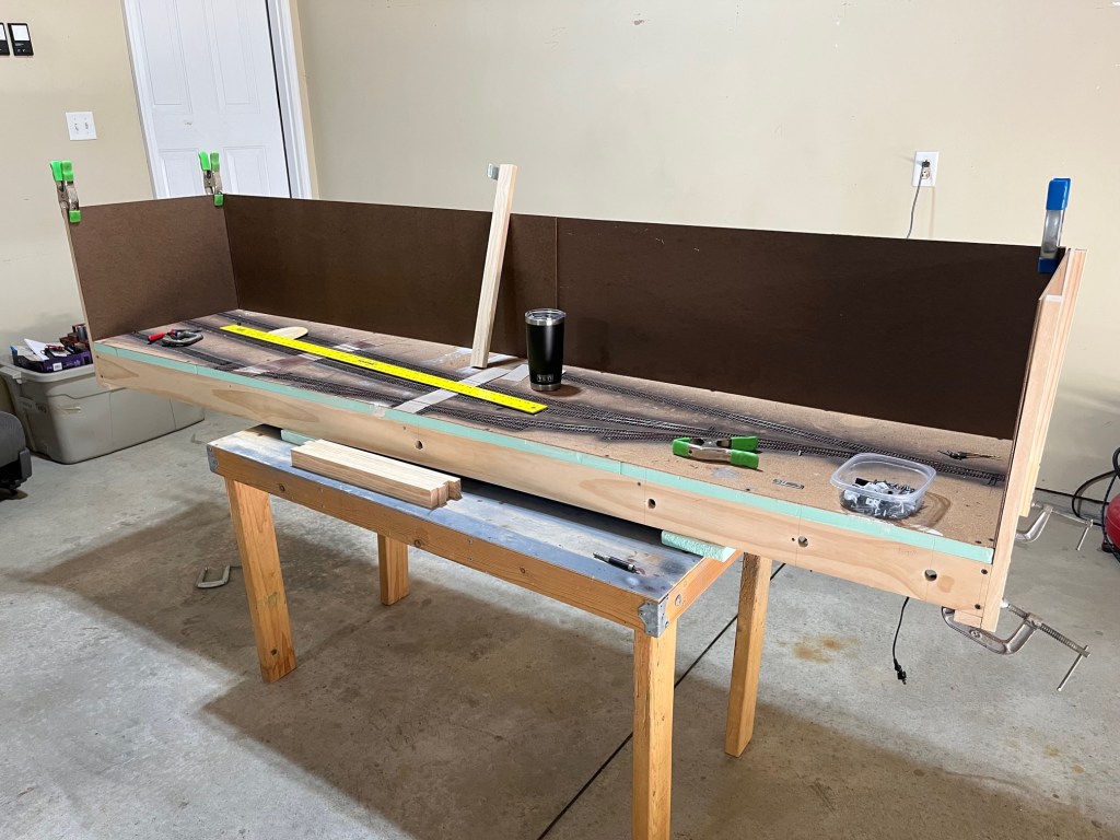
Below. In early July I rented a table saw from Home Depot, bought some 1 x 2s and 3/16-inch Masonite, and got to work. Here is the layout in the garage all set for backdrop installation. Looks like I’ve got a coffee ready too.

I decided to hang the backdrop in three sections. One small section for each end, and one long 7-1/2-foot section for the back. I ripped Masonite to a height of 14 inches and installed bracing behind it to secure it to the layout. It is easily removeable for painting and backdrop work.

Installation couldn’t be more simple. After a few hours I had both ends and the back side of the backdrops installed. I glued and screwed the 1 x 2 strips to the back of the Masonite; the clamps are holding everything in place while the glue dries.
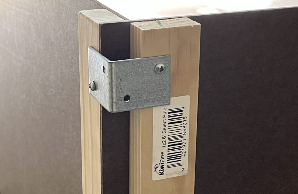
Below. Here’s a close-up of how the 1 x 2s are installed to support the backdrop. The clamps are cheap spring clamps I’ve had around the house for 20 years. This scene reminds me somewhat of the old article in MR that had a pictures of Andy Sperandeo building a layout based on the Santa Fe lines in Oklahoma. The caption read “Here’s Andy enjoying the hobby of C-clampling.” The humor there was so subtle it took me 20 years to understand it. I think the spring clamps would’ve made his work go faster.

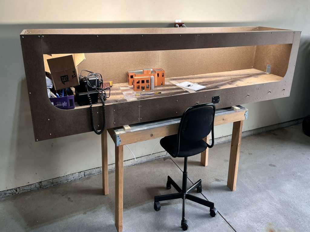
Below. Here’s the from behind the backdrop. You can see how each piece–the ends and the back part of the backdrop–are built to be easily removeable units. At the bottom right you can see that I drilled holes to pass cords through.

End clamps, screwed into the 1 x 2s, keep everything tight.
With the backdrops in place, I can cut and install the front fascia. I started with the foundation for the lights. I installed a long 1 x 4 L-girder and screwed it in place on the backdrop ends. Two LED tube lights will be installed behind the L-girder. You can see how low I’m installing that light bar. I want the layout to be a really tight shadowbox. I think the effect will be dramatic.

Next I installed the top and side fascia. This was easy but I took my time to try and get everything lined up and get really clean edges. The curved corners on the end fascia were something I had on the previous version of Hermitage Road, so I made sure I kept that feature on this version. I measured the curves on the ends with a paint can and drew the circle, and cut them slowly with a jig saw. Then I shaped the curves with sandpaper to clean them up.

The layout was turned upside down to install the lights. I bought two 5000-lumen LED fixtures from Menards and installed the behind the wood “sub-fascia” (if that’s a word). They were easy to install. I ran the wires through the backdrop sides and around behind the backdrop to a separate power strip.

After another hour of sanding, shaping, screwing and finally getting everything secured in place, here’s the layout at the end of the day. Electric switches are installed on the far right to control the four power turnouts, and the NCE plug-in is up front. I plan on installing a shelf along the front of the layout as well to hold uncoupling sticks, drinks and other important stuff.
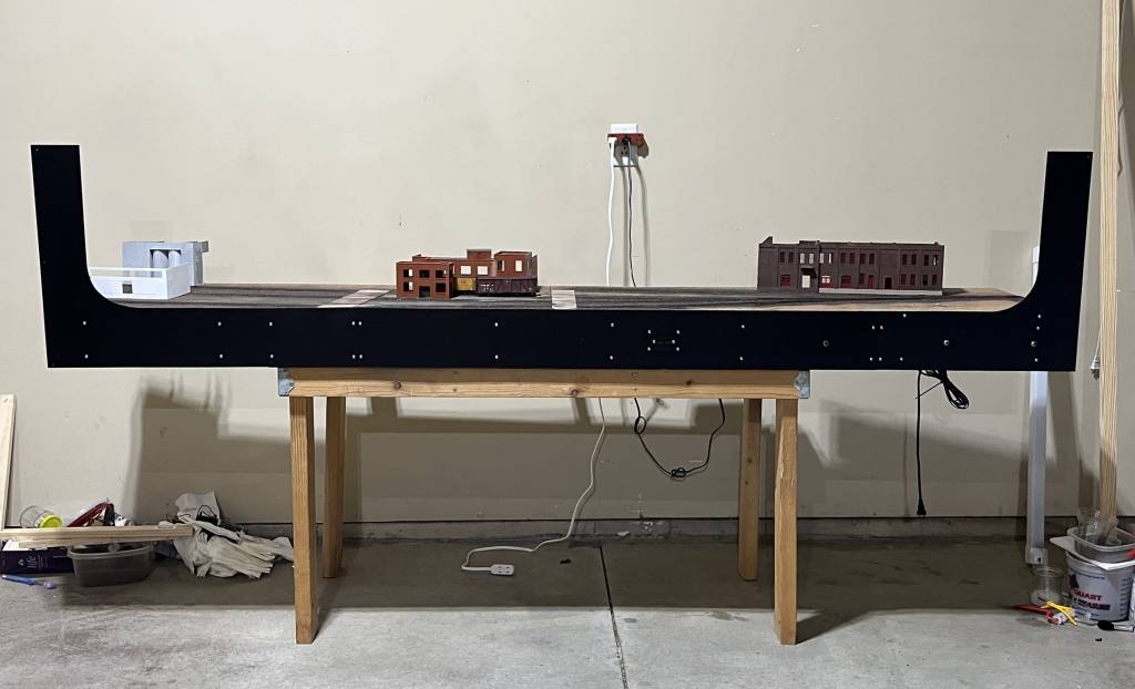
I’m getting a little ahead of myself here, but here’s what the layout looks like today, with the fascia partially painted and re-installed. It’s lookin’ good!
While I was installing the fascia I dropped my old, giant, heavy power screwdriver on the most important turnout on the layout–the wye at the entrance of the yard, seen at the bottom center below.
That wye turnout was an extensively rebuilt Shinohara switch since Micro Enginering doesn’t offer a wye. It was already fragile as it was. I bashed it good. Maybe next time I’ll try a Peco Code 75 wye to speed things along.

I smashed the points and destroyed all the working mechanism, and the detail parts went flying. I had to replace just about everything below the frog. As it is scratchbuilt, I had to get out all that track stuff and completely rebuild the darn thing. First I removed all the ties, de-soldered the points and built a replacement throwbar using a copper-clad tie. In the photo below you can clearly see the 1/2-inch tube I use as a channel for the Tortoise machine point-throwing rod.

An hour later here’s how it looked, below. I installed a new throw bar, replacement ties, replacement detail parts, and a new copper tie at the extreme end of the layout where the track will enter staging. It looks pretty sloppy, but after a little more cleanup, and paint and ballast, it’ll all blend in. There will be an overpass over this turnout so it will be partially obscured.

Well, that’s it. A pretty boring post, but necessary to publish to maintain the record. Ballasting next.
Oh, one last thing. Here’s a new freight car I got in July. This is one of the nice Rapido steel-sided B-50-16 cars. Ted Culotta, on his blog Prototype Railroad Topics, did a terrific review of these cars at https://prototopics.blogspot.com/2023/07/rapido-southern-pacific-b-50-15-ho.html. It’s worth a read. I’m fond of these cars, having seen and photographed a few in California back around 2000. I’ll have to dig out the slides and post them. The Rapido model is beautiful and I’m glad to have one in the fleet.

I hope you all enjoy your week and get some good modeling done! – John G

Nice artic
LikeLike