

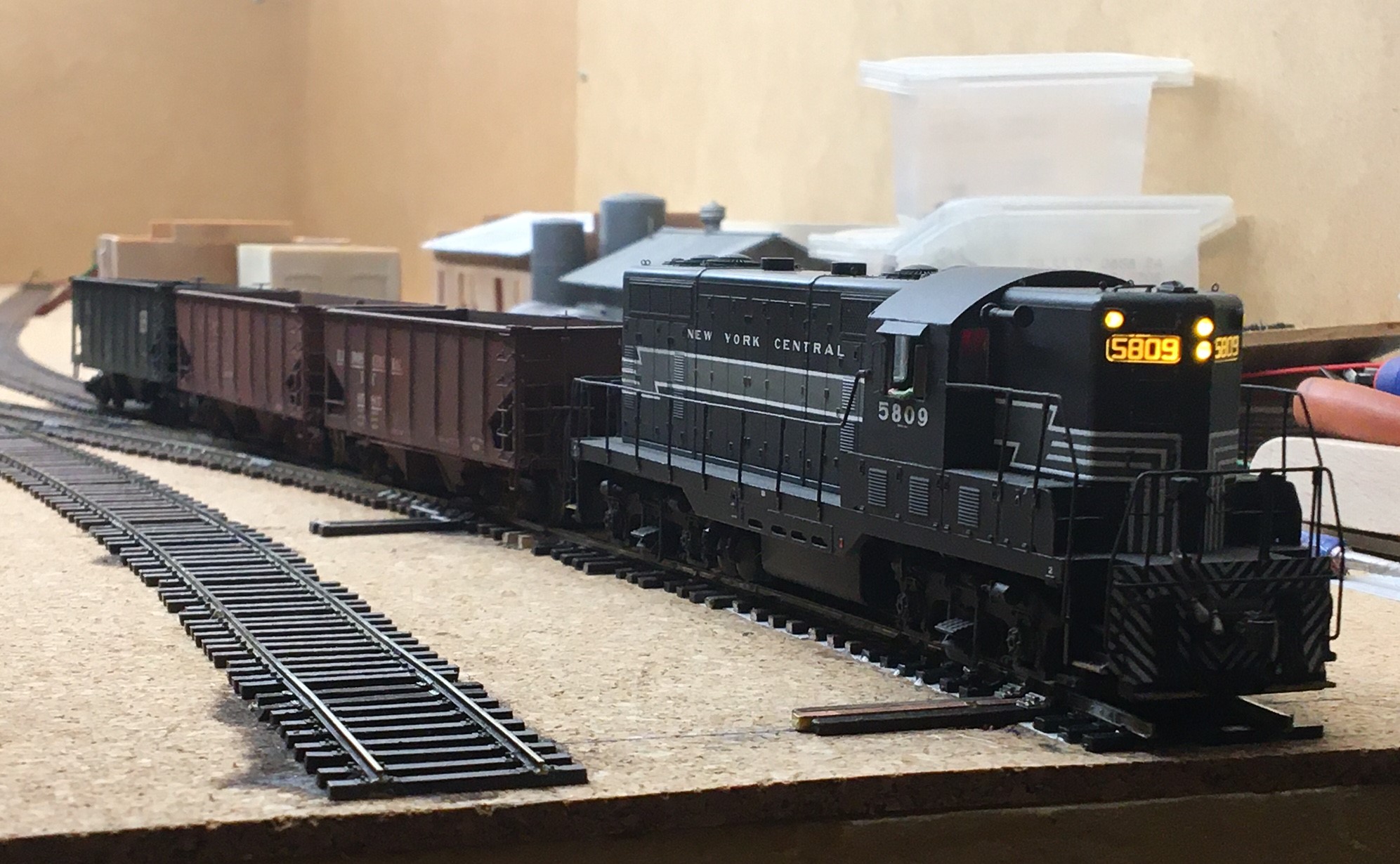
As of today, Hermitage Road is wired and mostly operational. The photo above shows the future SAL 1402, an engine leased–literally–from my friend John Moenius. John had two of the engines and wasn’t going to use them, so I offered lease one from him, just like the big railroads do. Lease Terms: One Dollar, but I’ve gotta decal, paint and weather it. The engine is equipped with a SoundTraxx Tsunami 2 DCC/sound chip and is the best runner I’ve got.
I was able to go from “wood to wired” and running trains in about 45 days thanks to using a lot of stuff leftover from the last layout, and getting organized before beginning construction.

I planned, and did some focused buying, and collected everything needed over a period of about 60 days. Then, around November 1st, I started building.
Below. Most of the lumber for Hermitage Road, not including the backdrop fascia. Most of it is recycled from the old Ackley layout. I cut it about a month before I started construction.
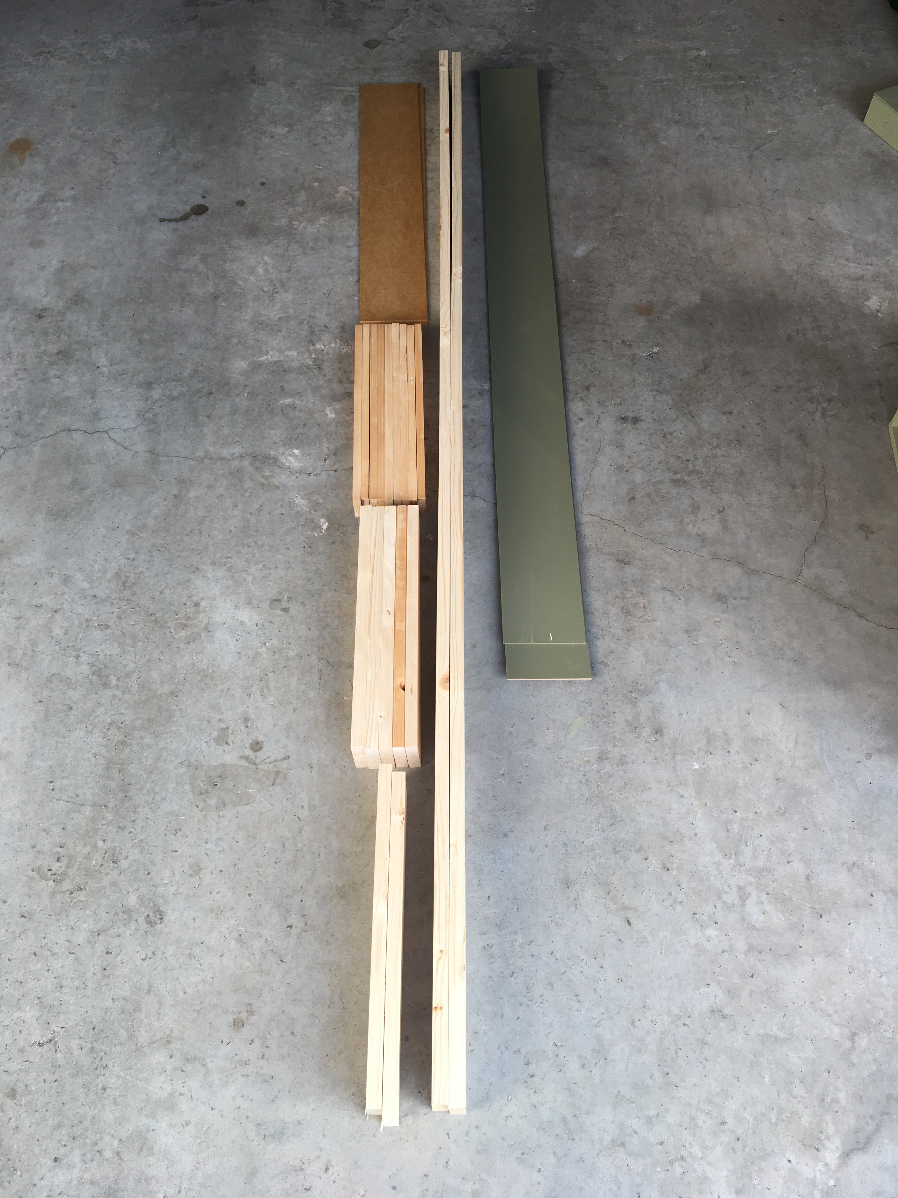
Below. I went to the local German hardware store and they cut up a massive piece of masonite for me. Free of course–service comes with the price.

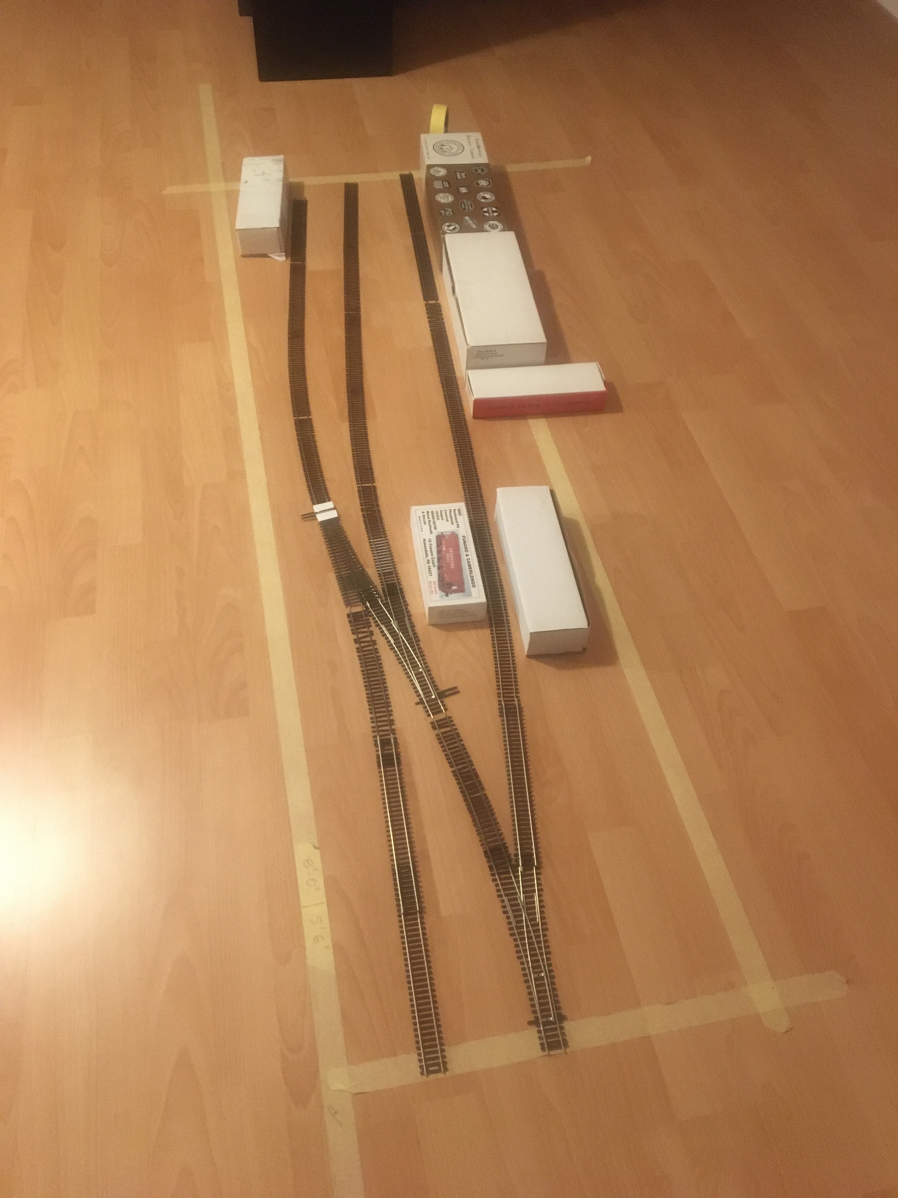
I mocked up the layout on the floor before beginning construction. I went through dozens of iterations, trying to get in everything I wanted while keeping it under 2 x 8 feet. Here’s one of the earlier five-feet-long mock-ups, below. The Richmond Cinder Block Co. is represented by the O scale boxes at the back right. The current track configuration is very close to this.
Layout Constraints
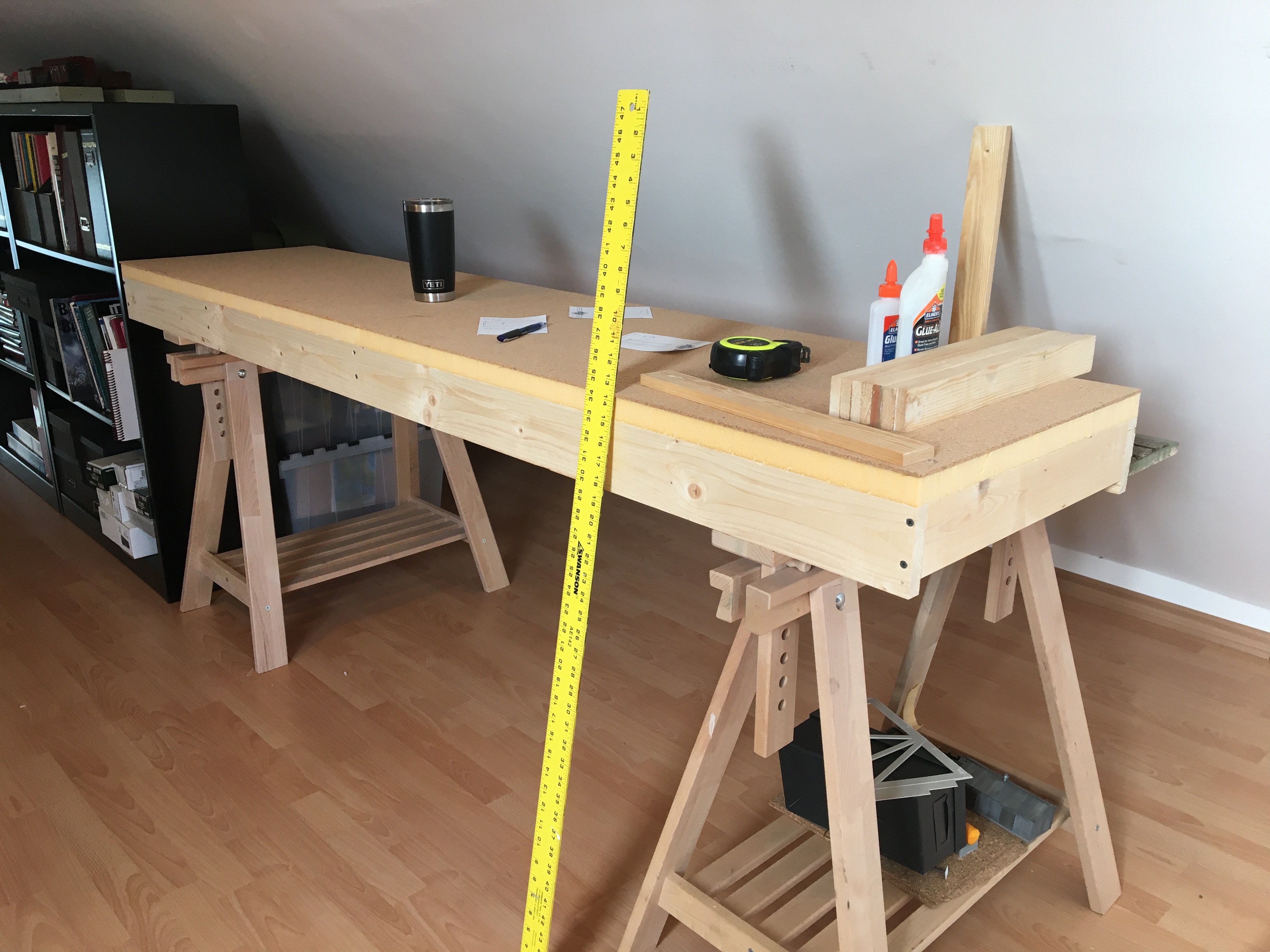
The first constraint I faced was there is only about 15 feet available for a layout, with the back of the layout against a sloped ceiling.

Second, because of the sloped ceiling, the layout is built at sit-down height, with the track elevation at 37 inches from the floor. Layout legs are simple–I’m re-using the Ikea Finnvard sawhorses from the Ackley layout, set at the “second peg”, making the Finnvard height 31 inches.
Backdrop height is 14 inches high to maximize as much space as possible against the sloped wall.
Benchwork was built in the traditional box-structure, 6-feet, 10 inches long and 17 inches wide. The subroadbed/layout base is made of a German product called “Styrodur” which is much like US blue styrofoam. Styrodur is more sturdy but is more brittle. I glued the Styrodur to the box frame and then screwed it down where possible to make sure of a secure fit.

Roadbed
Used 4mm cork sheet for roadbed. I ordered it from Amazon.de (“German Amazon”) and it was here the next day. I completely covered the Styrodur with the cork. It was simple and fast, and prototypical as most of the industrial tracks in this area were sunken into the ground over time.
Track and Turnouts
I used a combination of kit-bashed turnouts and Micro Engineering track. I used the Code 55 flex for almost all the tracks, but used all Code 70 turnouts. Two of the four turnouts are partially rebuilt Micro Engineering Code 70 #6s, and two are Shinohara #4 wyes that were almost completely rebuilt. I wanted to build all Code 55 turnouts but didn’t want to wait another 30-40 days so I could build them.

All four turnouts were rebuilt with frogs and detail parts from Proto87 Stores and Details West. The photo above is of one of the two rebuilt Shinohara wyes. I basically used the track, replaced the frog, and replaced everything else. Now it is DCC-friendly. The tie plates are from Proto87 Stores.
I’ll talk more about track in a later post.

Fascia and Valence
The fascia was cut from 3mm Masonite, once again left over from Ackley layout projects. I curved the fascia up at the ends about three or four inches from each end. See the photo below. I wanted to give the illusion that a few of the tracks continue past the valence and beyond the layout.
The light valance has two LED tube-lights mounted on the backs-side. These are German fixtures running at 220V.

Wiring
Once again, I used almost everything from the Ackley layout. I bought some new feeder wire, and a 50-pack of suitcase connectors on Amazon. That was it.
I wired the layout up via the standard method, soldering feeders every three or four feet and in the appropriate places on the turnouts. I also installed Tortoise switch machines for all four turnouts. I powered three of the frogs through the Tortoises and one using a Tam Valley Frog Juicer. I still like using switch machines; they keep hands out of the layout, but take a lot more installation time and fiddling during installation. Like the last Ackley layout the switch machines are controlled in front using small toggles.

Above. Testing the turnouts for power-routing problems. If there’s a problem, I mark it with a red pin and come back it to later.
Below. Under-layout wiring in progress. It’s messy work but was done in about a week.
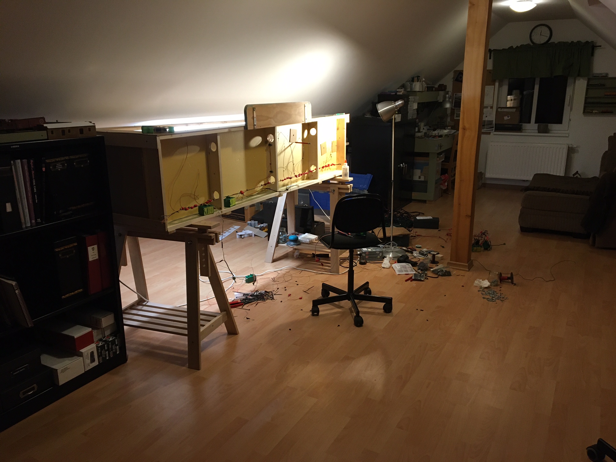
All wiring and plugs come out of the right side to make convenient connections the power system and the staging yard. Train control is my trusty NCE PowerPro.
Below. The wiring process in action!

That’s it for now. A not-very-exciting post but this one is important for archival reasons. Meanwhile the trains are running…
…and the track crew will be finishing a few more things to get ready for scenery.
I hope you have a wonderful weekend. God Bless America! – John G

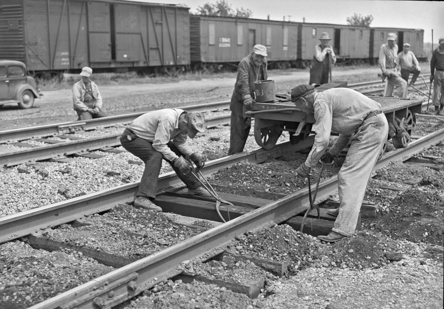
I assume from where they are placed that the weights in track laying the picture are switch locks. I use weathering pens for the side of track–O Scale–because besides painting the track they get some on spikes, tie plates and ties; and the variation of pressure causes fluctuations in the coloring
LikeLike
Excellent work! I’m enjoying following the progress. I have a similar sized layout (1.5×7.5 ft) that sits atop some IKEA shelves, and its neat how artistic it can look with good lighting and a valiance. I love that Seaboard switcher!
LikeLike