
So my wife called me at work this morning and announced “We are now on the Information B Highway!” We finally had our horrible satellite internet replaced this morning with a hybrid DSL-LTE thing that delivers faster internet service. It’s not the 100 megabytes/sec I had in Illinois–this is probably more like 20, which is why she said we’re on the B Highway (a reference to German B highways, that are not-quite-the-Autobahn).
Despite what you know about Germany, it is one of the lowest-rated countries in Europe when it comes to internet connectivity. In some places the internet is good; in many places it is laughable, in many other places it is non-existent. Up until today we lived in one of the “laughable” places. We could only get satellite internet which delivered a whopping one megabit/second speed (that’s 125k/sec). Until now I was unable to send any pictures anywhere, and pictures are what modelers thrive on.
Even more laughably, if that’s a word, our new, faster system is much less expensive. Only in Germany.
And now, on to some prototype modeling.
I’ve made a lot of progress on the layout in the last 45 days, mostly on small projects and mostly in small increments. It is amazing how a little bit of work every day can add up to big progress over a short time. Here are a few updates.
1 – The Farmer’s Field
I ordered one more package of Silflor #766-22 Agrarian Stipes with Leafs, Summer from Scenic Express and installed it right away to finish up the Farmer’s Field scene at the extreme north end of the layout. Like last time I simply put down a bead of Elmer’s Glue and glued the rows down and that was it.
The trouble was finding Elmer’s Glue. Every kid in the Western Hemisphere is using it to make “slime” and there has been International Elmer’s Glue-All Crisis for about three months.
Next I strung a few wires on the fence posts. I used EZ Line from Berkshire Junction. This is great stuff and I simply stretched it around the fenceposts, and tied it around a few, until the line went all the way around the fenceline. I installed two lines, one on top and one in the middle. I figured the bottom line would be obscured by grass (there are no weeds on my layout!) so I didn’t attempt to model it.

Above, here the stuff I used. I’ve probably had this stuff for 10-12 years. Below, here’s what it looks like stretched out and secured to the fenceposts. Not bad.

2 – Landforms
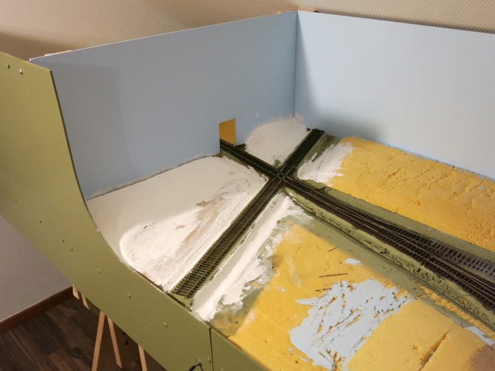
I finished the landforms on the layout over the last month. I covered the Styrofoam forms with Woodland Scenics Hydrocal and then painted them with water-based paint that I got at the local Obi Superstore here in Kaiserslautern. The paint is more like a paste and it covers really well, and because it is so thick it has a little gap-filling capability. Here’s an in-progress shot of the Hydrocal going over the south end of the layout by the IC crossing.
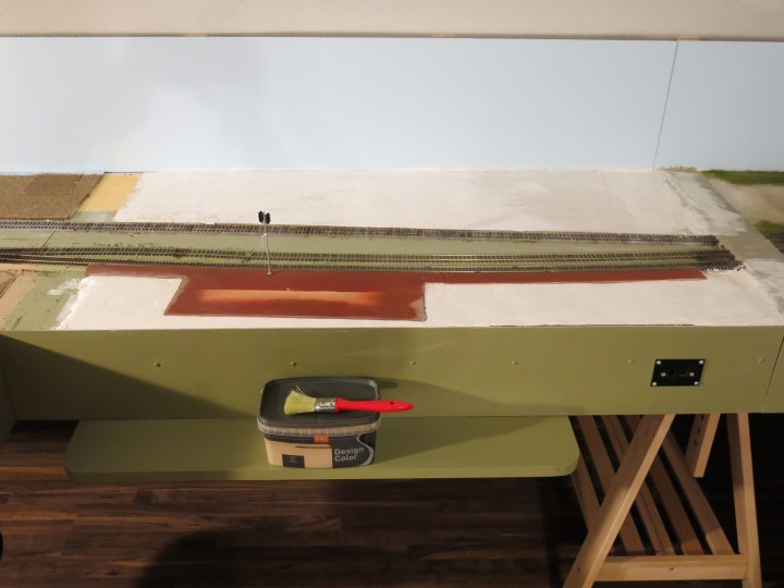
Below is the landform I built for the depot. I drew an outline of the depot platform and then removed it, and then applied about 1/4-inch of Hydrocal, as smooth as I could, to serve as a parking lot. I also applied Hydrocal between the road and the area where Scooter is sitting as well. I could not get these areas flat, so I went back over them several times with drywall patching compound and then I sanded it all down. Then I painted it with the same tan color I used for the rest of the landforms.
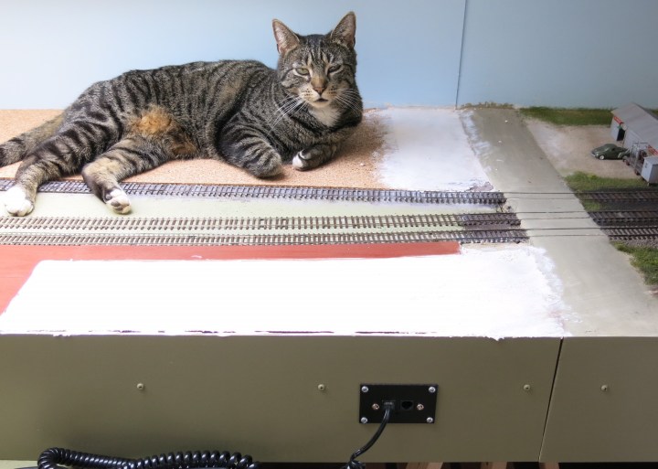
Below. Here’s what the depot parking lot looked like when I was done. I also put a very light coat of paster down on the other side of the tracks for the industries over there. The depot parking lot looks good from three feet, but up close it looks “nicht so gut”.

Above. This is the area around the interlocking tower, on the south side of the layout, after completing the Hydrocal and sanding it down a little bit. I mixed a lot of the water-based paint into the plaster to cut down the brightness of the dry Hydrocal.
Next I smoothed out an area for the interlocking tower, using a wet sanding sponge. I want this area to appear well-worn, and flat.

I want the ends of the ties to be exposed per prototype photos of the era, so I trimmed the roadbed back to the ends of the ties to make that job easier. Then I sanded down everything lightly with a sanding sponge…
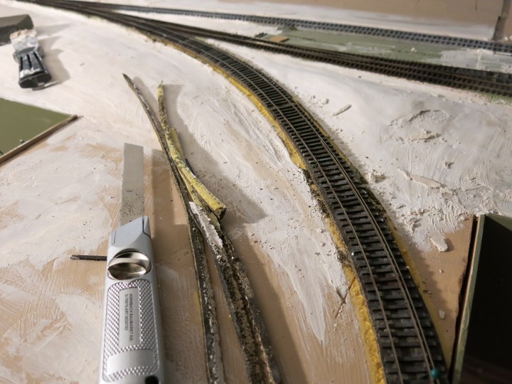
…and then gave it all a coat of paint. And that’s it. All ready for ballast and static grass.
3 – Illinois Central Train Order Signal
I made my first order to Shapeways last month and got the parts before I left for St. Louis RPM. I want to build an IC train order signal at the IC-M&StL junction on my layout and searched everywhere for a suitable signal arm. The prototype tower did not have such a signal (it was at the IC depot west of the crossing) but I thought it was important to add it to help set the time and place. Finally I came across this:
The description of the signal arms says “SP” but I compared them to several pictures of IC signals and they looked very similar. I ordered the set about a month ago and got the box after a short ten-day wait. I think I paid about $14 and that included shipping. I thought the service to German was pretty fast.
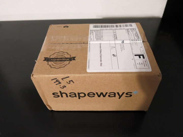
They even sent me an e-mail a few days after my order and told me “We’re printing your item!” The only thing in this huge box were these little signal blades:

Here’s a prototype photo of an IC lower quadrant train-order signal. The models I have are SP, but they’re really, really close to the signals in the photo. John P. Vander Maas Collection, Waterloo, Iowa. May 1956.

The signal arms are very interesting. You can see the printing lines but with a coat of paint they should disappear. There are no roundels so making something to fit will be a challenge. My signal will be non-operating but I would like it to be lit if possible so maybe I can use “tab” material (you know–the plastic tabs on paper folders) to make the glass. Come to think of it, that old Microscale material might work better. You know, the stuff you use to make windows with.
I planned on scratchbuilding the mast but found, in my signal parts box, a complete mast assembly from a Tomat upper-quadrant train order signal (see below). I meant to use this for a Seaboard signal but never completed the project. The signal mount on the top of the Tomar signal was oriented the wrong way, so I removed the bulb, heated up the top of the signal with a soldering iron, and moved the signal mount 90 degrees. That would put the signal in the correct orientation, with the ladder facing the tower and the mount facing each side of the track. I also changed out the awful-looking round signal mount on the bottom of the signal with something more prototype-looking that I had on hand. The new mount is a Integrated Signal Systems product.
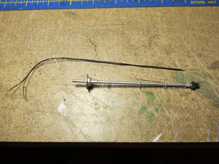
The signal mount on the top of the Tomar signal was oriented the wrong way, so the first thing I did was remove the bulb and heat up the top of the signal with a soldering iron, and moved the signal mount 90 degrees. That put the signal mount in the correct orientation, with the ladder facing the tower and the mount facing each side of the track. That only took a couple of minutes.
I also changed out the awful-looking round signal mount on the bottom of the signal with something more prototype-looking that I had on hand. The new mount is a Integrated Signal Systems product. I just heated it up and it popped right off. After a little sanding and shaping I was able to fit the new part on, then just used ACC to secure it in place.

Here’s the completed mast assembly. That took a whole ten minutes.
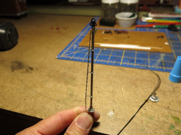
Next I played around with the signals and glued one on the mast to see how it would looks. Not bad!

I’ll send an update on this signal when I get done with the project.
4 – Electrical Plan
A huge issue here is power conversion. Of course all of my model railroad equipment is 110-volt, but my house runs on 220. Everything has to run through a converter. Converters are expensive and they use a ton of power, and can’t be left on overnight. I have one for the layout but needed a plan to route power from the wall to the converter and then out to the various places where power was needed. So here is the plan:
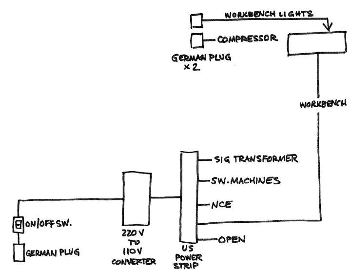
The plan is set up to provide one On-Off switch for the whole layout. I’m using an outlet adapter with a built-in On-Off switch as my master On-Off switch. It has a little green light on it to let me know if it’s on. That outlet adapter runs to the 220 volt-to-11 volt power converter, which then runs to a US power strip. From there, I can run the layout and even have a line strung behind the layout to the workbench.
The whole reason for using an On-Off switch is because the power converter uses a ton of energy. We don’t leave them on if we don’t have to. So having a lit On-Off switch near the room entry reminds me to turn the layout power off when I leave the room for the day.
I’ll post a few photos of the set up when it get everything wired and looking good and organized.
5 – Progress Pictures
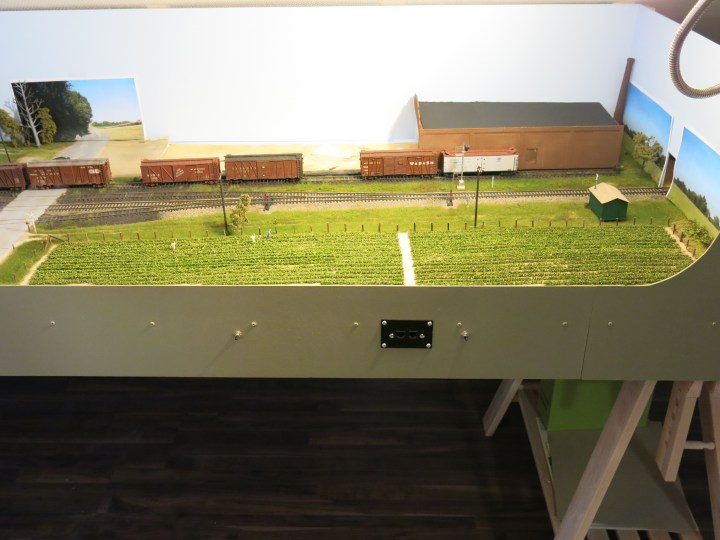
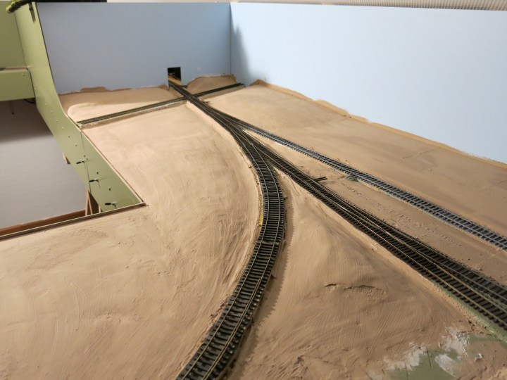
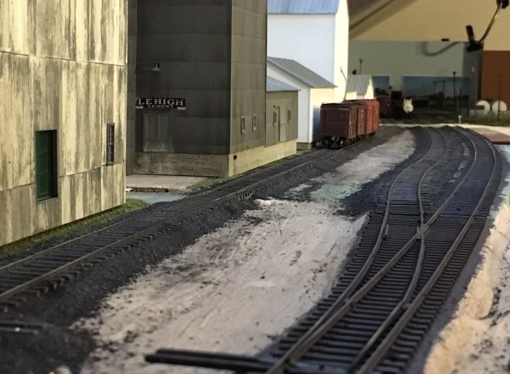
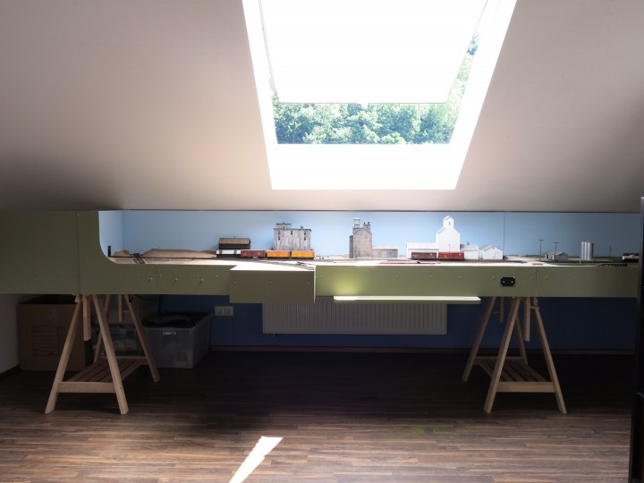
Below. An interesting picture I took with my son’s iPhone 6. The depth of field is amazing compared to my other more expensive cameras. This photo shows some of the south side track already ballasted (I’m covering that in the next few posts).
Here’s another picture, below, of the south end of the layout as it looks today. The skylight over the layout is a blessing and a curse: A blessing in the winter because it provides a little light, a curse in the summer since it heats up the room. Most houses in Germany don’t have air conditioning so skylights are house-heaters in the summer.
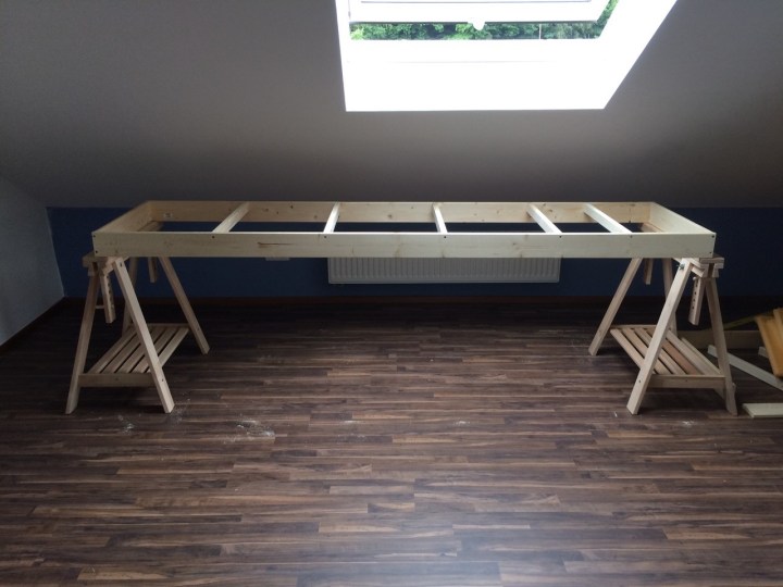
It is just about July 4th, 2017. Here is where I was at the end of the day, July 4th, 2016:
That’s all for now!

Hi John,
I find that the build lines on Shapeways parts do show through after painting so I run some 400 or 600 grit paper lightly over them prior to painting. I hear that some modellers prime them first (e.g. Tamiya Fine Surface Primer) but I haven’t had any issues shooting Polly Scale type paint directly onto the parts (although my parts are quite small – e.g. truck-mounted ATS pick-up shoe, Elesco feedwater heater, etc).
Love your posts. A pleasure to read.
Cheers
LikeLike